


Meter to Flow Computer Communication Worksheet 328
Reference, Installation, and Operations Manual Meter setup and configuration worksheet
3-9000-743 Rev S June 2013
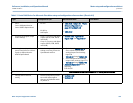
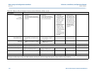
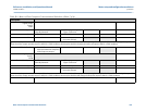
Digital Output
Group 2
DO2A
Electrical Configuration • TTL
“Internally Powered”
• OC
“Open Collector”
Content • Flow Direction • Flow Validity
Polarity • Normal • Inverted *
(see note below)
*Note: Inverted operation - Use if the output of the ultrasonic meter is reversed from what a flow computer is expecting. Selecting the check box inverts the digital output. This
means that if the output normally outputs a HIGH for a TRUE condition, selecting this check box changes the output to output a LOW for a TRUE condition.
Full Scale Flow Rate • Enter the flow rate to be equiva-
lent to the maximum frequency
of the frequency output.
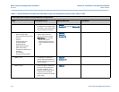
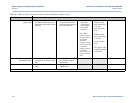
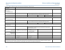
Digital Output
Group 2
DO2B
Electrical Configuration • TTL
“Internally Powered”
• OC
“Open Collector”
Content • Flow Direction • Flow Validity
Polarity • Normal • Inverted *
(see note below)
*Note: Inverted operation - Use if the output of the ultrasonic meter is reversed from what a flow computer is expecting. Selecting the check box will invert the digital output. This
means that if the output normally outputs a HIGH for a TRUE condition, selecting this check box will change the output to output a LOW for a TRUE condition.
Full Scale Flow Rate • Enter the flow rate to be equivalent to the maximum frequency of the frequency output.
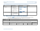
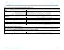
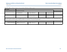
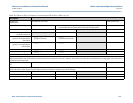
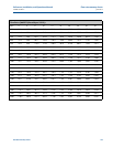
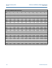
Table E-2 Meter to Flow Computer Communication Worksheet (Sheet 7 of 9)
Description