


Reference, Installation, and Operations Manual Section 3: Installation
3-9000-743 Rev S June 2013
Transducer cables/appropriate transducer 57
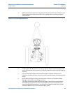
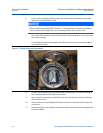
12. Re-assemble Base Unit electronics in reverse order (note the transducer wiring for J1
and J2 as shown on the Acquisition board label:
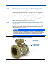
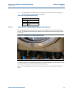
3.3.4 Transducer cables/appropriate transducer
The A1 cable should be connected to the transducer assembled in the meter body transducer
port A1. This procedure should then be repeated in numerical order for each one of the other
transducers.
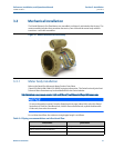
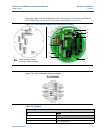
Figure 3-13 Transducer Ports and Cables Base Unit
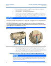
The meter body ports are identified by stamped or cast lettering adjacent to the transducer port
counter bore and on tags attached to the transducer flanges.
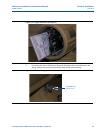
Remove the metal plug from the side of the electronics enclosure to expose the field wiring
entry.
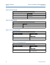
Table 3-6 Acquisition board wiring
Acquisition board wiring
(+) White or Blue
(-) Black or Gray
SShield