


Reference, Installation, and Operations Manual Section 3: Installation
3-9000-743 Rev S June 2013
Wiring and Connections 65
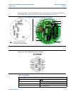
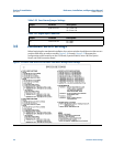
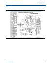
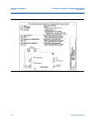
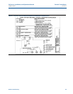
The default field connectors and pinouts for the Field Connection Board and the CPU Board are
shown in the following tables (Tab le 3-2 2 through Tabl e 3- 24 ). (Refer to Daniel Drawing
DE-21056, see Appendix I.)
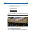
A DIN 41612 48-pin connector is the interface from the CPU Board to the Field Connection
Board (male end located on the back of the Field Connection Board).
5NC
TX
- RX/TX-
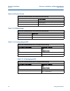
Table 3-20 J16 Port C
Power and Communications Field Connection Board Wiring
J16 Port C RS-232 RS-485
Pin Half Duplex
1RX RX/TX+
2TX
RX/TX
-
3 COMM_GND COMM_GND
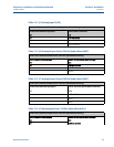
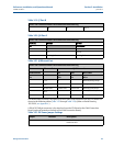
Table 3-21 J8 Ethernet Port
Power and Communications Field Connection Board Wiring
J8 Ethernet Port RJ45 Connections
Field Conn Bd. PC HUB Wire Color
Pin Pin Pin Wire
1
TX
+
31 White w/Orange Stripe
2
TX
-
62 Orange w/White Stripe
3 Chassis Gnd Chassis Gnd Chassis Gnd White w/Green Stripe
4
RX
+
13 Blue w/White Stripe
5
RX
-
2 6 Green w/White Stripe
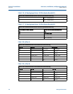
Table 3-22 DC Power Jumper Settings
Jumper Location Description
J2 Field Conn. Bd. PWR 1 +24V (polarity insensitive)
PWR 2 24V RET-
Table 3-19 J7 Port B
Power and Communications Field Connection Board Wiring