


Reference, Installation, and Operations Manual Section 7: Maintenance and troubleshooting
3-9000-743 Rev S June 2013
Removal without Extractor Tool 265
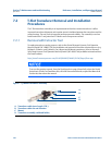
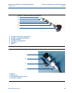
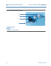
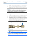
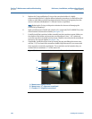
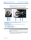
7.2.2 Removal without Extractor Tool
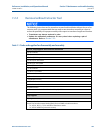
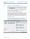
Table 7-1 Tools and supplies for disassembly and assembly
Tool list, shop supplies and reference documents
3/8” drive ratchet
3/8” drive extension
3/8” drive 7/16” deep socket
3/8” drive 5/16” hex socket
3/8” drive 1/2” hex socket
3/8” to 1/2” driver adapter
1/2” drive ratchet
1/2” drive 1 1/4” Socket
1 1/4” combination wrench
1 1/8” combination wrench
1” combination wrench
3/16” flat Blade screw driver
1/16” Xcelite Hex driver
6mm Allen wrench
N.A.S. Loctite Nickel Anti-Seize 16 oz. Brush Top P/N 77164
Molykote 111
Shop supplies
Shop rags
Adhesive stickers for the cable nuts
Sharpie Fine Point Permanent Marker (Black) Series # 30000, to label transducers:
• A1, A2, B1, B2, C1, C2, D1 and D2 for SeniorSonic meters
• A1, A2, B1 and B2 for Juniorsonic meters)
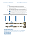
The following instructions are for transducer removal and installation without the use of an
extractor tool. It is recommended that one work on one transducer assembly at a time to
reduce the possibility of improper assembly with respect to transducer lengths and location.
• Transducers are always replaced in pairs.
• Update the calibration parameters for every chord when replacing a pair of
transducers. Refer to Section 7.2.5.