


268 Installing the transducers
Section 7: Maintenance and troubleshooting Reference, Installation, and Operations Manual
June 2013 3-9000-743 Rev S
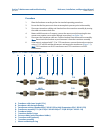
5. Replace the O-ring and Backup O-ring on the transducer holder. It is highly
recommended that the O-rings be replaced when the transducer is removed from the
holder or stalk. Make sure that the contoured side of the ring is facing away from the
mount. Lubricate with Molykote111 Silicone Grease or equivalent.
Note: Replacing the O-rings at this point minimizes the chances of damaging the
transducer by dropping it.
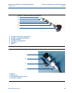
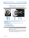
6. Apply a small amount of nickel anti-seize (N.A.S.) compound (P/N 2-9-9960-134) to the
outer threads of the transducer holder (see Figure 7-6).
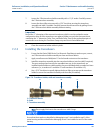
7. Carefully install the transducer holder assembly into the transducer mount. Make sure
the threads of the holder and mount are correctly aligned. Use a 1 1/4” socket and
screw the transducer assembly into the mount. Tighten to securely seat the assembly in
the mount. Do not over tighten (see Figure 7-8).
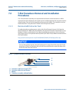
8. If applicable, install the mount cover by rotating the tag and sliding the mount cover
over the 1 1/4” hex head of the transducer holder. Align the mount’s two screws with
their respective screw holes and tighten. The screw holes can be located as they are
marked with an arrowhead, “V” on the mount rim.
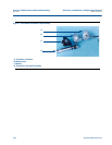
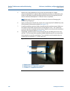
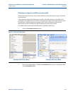
Figure 7-7 M-mount cover and chordset with “V” arrowhead mark
A.
B.
C.
A. Mount cover captive screws
B. Mount cover “V” alignment arrowhead
C. Chordset “V” alignment arrowhead