


Reference, Installation, and Operations Manual Section 6: Meter operation
3-9000-743 Rev S June 2013
Digital outputs 219
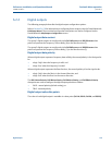
6.2.2 Digital outputs
The following paragraphs describe the digital output configuration options.
Refer to Section 5.6.10 for information on configuring these outputs using the Daniel MeterLink
Field Setup Wizard. The associated configuration data points can also be configured via the
Daniel MeterLink
Edit/Compare Configuration screen.
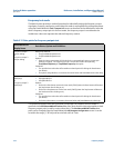
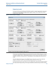
Digital output data content
The group 1 digital outputs are configured via the DO1AContent and DO1BContent data
points to represent the Frequency 1 data validity (0) or the flow direction (2).
The group 2 digital outputs are configured via the DO2AContent and DO2BContent data
points to represent the Frequency 2 data validity (1) or the flow direction (2).
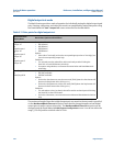
Digital output data polarity
When a digital output represents frequency data validity, the normal polarity is for the signal to
be:
• a logic ‘high’ when the frequency is valid, and
• a logic ‘low’ when the frequency is invalid.
When a digital output represents the flow direction, the normal polarity is for the signal to be:
• a logic ‘high’ when the flow is in the forward direction, and
• a logic ‘low’ when the flow is in the reverse direction.
The DO1AIsInvPolarity, DO1BIsInvPolarity, DO2AIsInvPolarity, and DO2BIsInvPolarity
data points are used to configure the digital output polarities as follows:
• FALSE - normal polarity (default setting), or
• TRUE - inverted polarity
Digital output value data points
The value of each digital output is readable via a data point (DO1A, DO1B, DO2A, and DO2B).