


Reference, Installation, and Operations Manual Section 7: Maintenance and troubleshooting
3-9000-743 Rev S June 2013
Installing the transducers 269
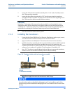
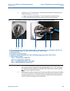
9. If replacing T-21 or T-22 transducers, install the keyed transformer assembly into the
transducer holder (see Figure 7-8).
a. Apply a small amount of Molykote 111 to the transformer assembly O-ring.
b. Insert the keyed transformer into the back end of the transducer holder.
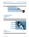
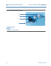
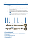
Figure 7-8 T-22 transducer assembly, holder, transformer, retainer, cable nut and chordset
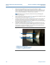
10. For T-21 and T-22 transducers, place the retainer over the transformer assembly. Ensure
the retainer threads are aligned correctly and hand-tighten. Use a 1 1/8” wrench and
turn clockwise until the transformer assembly is fully seated in the transducer holder.
Note: Do not over tighten the retainer.
11. Reconnect the transducer chordset to the transducer holder or the retainer if installing
T-21 or T-22 transducers. The internal connector of the transducer chordset is keyed
and will only go on one way. Secure the transducer cabling nut by turning clock-wise.
Ensure the cable nut threads are correctly aligned.
A.
B.
C.
E.
F.
A. T-21 transformer assy. (W-01 P/N 1-360-03-090) or T-22 transformer assy. (W-02 P/N 1-360-03-110)
B. Transducer holder (Type - H1 P/N 1-360-01-128, H2 P/N 1-360-01-228)
C. Mount and holder
D. Transducer port (meter body)
E. Transducer retainer (Standard P/N 1-360-01-958) High temperature (P/N 1-360-01-978)
D.
F. Cable nut and chordset:
100
o
C - 5’ length P/N 2-3-3400-190)
100
o
C -15’ length (P/N 2-3-3400-194
200
o
C - Straight backshell (P/N 1-36-01-800)
200
o
C - 90
o
backshell (P/N 1-360-01-801)