6. Restore control system power (the LID displays, COM-
MUNICATION FAILURE at the bottom of the screen).
7. Access the SERVICE menu. Highlight and select
the ATTACH TO NETWORK DEVICE screen. Press
the ATTACH softkey. (The LID displays, UPLOAD-
ING TABLES. PLEASE WAIT; then, COMMUNICA-
TION FAILURE.) Press the EXIT
softkey.
8. Turn off control power.
9. Mount the new module in the unit control box using a
long-shaft Phillips screwdriver and the screw saved in
Step 4 on page 98. Make sure that the green grounding
wire is reinstalled along with the mounting screw.
10. Connect the LID communication wires (CCN bus) and
the power wires. If CCN wiring has been attached to the
CCN bus, disconnect the wires. Attach the sensor bus
plug and the input and output plugs.
11. Carefully check all wiring connections before restoring
power.
12. Restore control power and verify that the red and green
LEDs on the PSIO are functioning properly.
13. The LID should indicate AVAILABLE MEMORY and
a value. This value should start to decrease. (If it does
not, check the LID wiring to the PSIO; ensure connec-
tion to the proper plug.) The bottom of the screen dis-
plays, UPLOADING TABLES, PLEASE WAIT.
14. After the PSIO tables have been uploaded into the LID,
access the STATUS01 screen. Move the highlight bar to
the TOTAL COMPRESSOR STARTS line. Press the
SELECT
softkey and then, using the INCREASE or
DECREASE
softkeys, change the value until it is the
same as the value from the old module. Press the
ENTER
softkey to save this value.
15. Move the highlight bar to the COMPRESSOR
ONTIME line. Press the SELECT
softkey and the, us-
ing the INCREASE
or DECREASE softkeys, change
this value until it matches the old module run hours. Press
the SELECT
softkey to save this value.
16. Change the address of the PSIO In the CONTROLLER
IDENTIFICATION table back to its previous value. Write
the address on the PSIO.
17. Use the configuration sheets (pages CL-3 to CL-11) to
input set point, configuration, and schedule information
into the PSIO. The TIME AND DATE table from the
SERVICE menu must also be set. A Building Supervi-
sor terminal can be used to download the old configu-
ration into the PSIO.
18. Access the CONTROL TEST table and perform the con-
trol tests to verify all that all tested functions are work-
ing properly.
If the software version has been updated, a CCN down-
load of the configuration will not be allowed. Configure
the PSIO by hand, and upload the PSIO into the net-
work using the ATTACH TO NETWORK DEVICE
screen.
19. Restore the chiller to normal operation; calibrate the mo-
tor amps.
PHYSICAL DATA AND WIRING
SCHEMATICS
Tables 15-26 and Fig. 56-61 provide additional informa-
tion regarding compressor fits and clearances, physical and
electrical data, and wiring schematics for operator conve-
nience during troubleshooting.
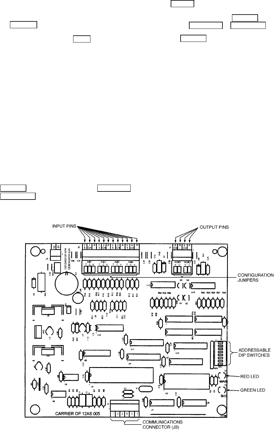
Fig. 55 — 4-In/2-Out Module
99


