


NOTE: When an alarm is detected, the LID default screen
freezes (stops updating) at the time of alarm. The freeze en-
ables the operator to view the chiller conditions at the time
of the alarm. The status tables show the updated informa-
tion. Once all alarms have been cleared (by pressing the
RESET
softkey), the default LID screen returns to normal
operation.
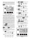
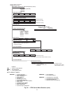
LID DEFAULT SCREEN MENU ITEMS — To perform
any of the operations described below, the PIC must be pow-
ered up and have successfully completed its self test.
The default screen menu selection offers four options
(STATUS, SCHEDULE, SETPOINT, and SERVICE). The
STATUS menu allows viewing and limited calibration/
modification of control points and sensors, relays and con-
tacts, and the options board. The SCHEDULE menu allows
viewing and modification of the Local Control, CCN Con-
trol, and Ice Build time schedules. Numerous set points in-
cluding Base Demand Limit, LCW, ECW, and Ice Build can
be adjusted under the SETPOINT menu. The SERVICE menu
can be used to revise alarm history, control test, control al-
gorithm status, equipment configuration, equipment service,
time and date, attach to network, log out of device, control-
ler identification, and LID configurations. Figures 15 and 16
provide additional information on the menu structure.
Press the MENU
softkey to select from the 4 options.
To view or change parameters within any menu structure,
use the SELECT
softkey to choose the desired table or
item. The softkey modification choices displayed will de-
pend on whether the selected item is a discrete point, ana-
log point, or an override point. Press the softkey that cor-
responds to your configuration selection or press the
QUIT softkey. If the QUIT softkey is depressed, the
configuration will not be modified. Use the following soft-
keys to access and select the desired section.
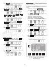
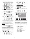
MENU STRUCTURE — To perform any of the operations
described below, the PIC must be powered up and have suc-
cessfully completed its self test.
• Press MENU
to select from the four available options.
• Press the softkey that corresponds to the desired menu
structure.
• Press NEXT or PREVIOUS to highlight the desired
entry.
• Press SELECT to access the highlighted point.
• Press QUIT to leave the selected decision or field with-
out saving any changes.
• Or, press ENTER to leave the selected decision or field
and save changes.
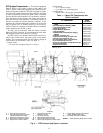
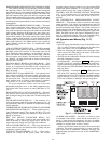
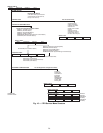
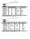
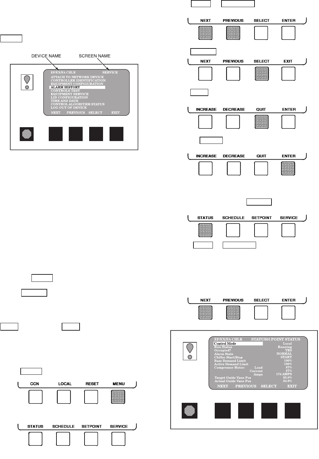
TO VIEW OR CHANGE POINT STATUS (Fig. 13) — Point
Status is the actual value of all of the temperatures, pres-
sures, relays, and actuators sensed and controlled by the PIC.
1. On the Menu screen, press STATUS
to view the list of
Point Status tables.
2. Press NEXT or PREVIOUS to highlight the desired
status table. The list of tables is:
• STATUS01 — Status of control points and sensors
• STATUS02 — Status of relays and contacts
• STATUS03 — Status of both optional 8-input modules
and sensors
• STATUS04 — Gear oil temperature and pressure
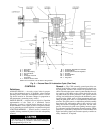
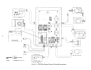
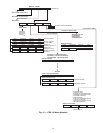
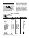
Fig. 12 — LID Service Screen
Fig. 13 — Example of Point Status Screen
(Status01)
17