


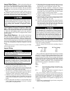
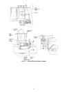
Inspect Water Piping — Refer to the piping diagrams
provided in the certified drawings and the piping instruc-
tions in the 17EX Installation Instructions manual. Inspect
the piping to the cooler and condenser. Be sure that flow
directions are correct and that all piping specifications have
been met.
Piping systems must be properly vented, with no stress on
the waterbox nozzles and covers. Water flows through the
cooler and condenser must meet job requirements. Measure
the pressure drop across the cooler and condenser.
Water must be within design limits, clean, and treated
to ensure proper chiller performance and reduce the po-
tential of tube damage due to corrosion, scaling, or ero-
sion. Carrier assumes no responsibility for chiller dam-
age resulting from untreated or improperly treated
water.
Check Optional Pumpout Compressor Water Pip-
ing —
If the optional pumpout system is installed, check
to ensure that the pumpout condenser water has been piped
in. Check for field-supplied shutoff valves and controls as
specified in the job data. Check for refrigerant leaks on field-
installed piping.
Check Relief Devices — Be sure that relief devices
have been piped to the outdoors in compliance with the lat-
est edition of ANSI/ASHRAE (American National Stan-
dards Institute/American Society of Heating, Refrigeration,
and Air Conditioning Engineers) Standard 15 and applicable
local safety codes. Piping connections must allow for access
to the valve mechanism for periodic inspection and leak
testing.
Relief valves are set to relieve at the 225 psig (1551 kPa)
chiller design pressure.
Inspect Wiring
Do not check voltage supply without proper equipment
and precautions. Serious injury may result. Follow power
company recommendations.
Do not apply any kind of test voltage, including to check
compressor oil pump even for a rotation check, if the
chiller is under a dehydration vacuum. Insulation break-
down and serious damage may result.
1. Examine wiring for conformance to job wiring dia-
grams and to all applicable electrical codes.
2. Compare the ampere rating on the starter nameplate with
the compressor nameplate. The overload trip amps must
be 108% to 120% of the rated load amps.
3. The starter for a centrifugal compressor motor must con-
tain the components and terminals required for PIC re-
frigeration control. Check the certified drawings.
4. Check the voltage to the following components and com-
pare to the nameplate values: compressor and gear oil
pump contactors, pumpout compressor starter, and power
panel.
5. Be sure that fused disconnects or circuit breakers have
been supplied for the compressor and gear oil pumps,
power panel, and pumpout unit.
6. Check that all electrical equipment and controls are prop-
erly grounded in accordance with job drawings, certi-
fied drawings, and all applicable electrical codes.
7. Make sure that the customer’s contractor has verified
the proper operation of the pumps, cooling tower fans,
and associated auxiliary equipment. This includes en-
suring that motors are properly lubricated, have proper
electrical supply, and have proper rotation.
8. Tighten all wiring connections to the plugs on the SMM,
8-input, and PSIO modules.
9. Ensure that the voltage selector switch inside the power
panel is switched to the incoming voltage rating, 115 v.
The 230 v alternative is not used.
10. On chillers with free-standing starters, inspect the power
panel to ensure that the contractor has fed the wires into
the bottom of the panel. Wiring into the top of the panel
can cause debris to fall into the contactors. Clean and
inspect the contactors if this has occurred.
Voltage to terminals LL1 and LL2 comes from a con-
trol transformer in a starter built to Carrier specifica-
tions. Do not connect an outside source of control power
to the compressor motor starter (terminals LL1 and LL2).
An outside power source will produce dangerous volt-
age at the line side of the starter, because supplying volt-
age at the transformer secondary terminals produces in-
put level voltage at the transformer primary terminals.
CHECK INSULATION RESISTANCE — Before applying
operating voltage to the motor, whether for checking rota-
tion direction or for actual operation, measure the resistance
of the stator winding insulation.
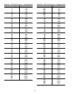
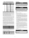
The test voltage, based on the motor operating voltage, is
as follows:
Operating Voltage DC Test Voltage
0- 900 500
901- 7000 1000
7001-14500 2500
This is particularly important if the motor may have been
exposed to excessive dampness either during transit or while
in storage. A ‘‘megger’’type instrument can be used to mea-
sure the insulation resistance. The test voltage should be ap-
plied between the entire winding (all winding leads connected
together) and ground for approximately one minute with the
winding at ambient temperature. The recommended mini-
mum insulation resistance is determined as follows:
RM = KV + 1
Where
RM = Recommended minimum insulation resis-
tance in megohms at 104° F (40° C) of the
entire winding.
KV = Rated motor terminal to terminal voltage in
kilovolts (1000 volts = 1 KV).
On a new winding, where the contaminant-causing low
insulation resistance is generally moisture, drying the wind-
ing through the proper application of heat normally in-
creases the insulation resistance to an acceptable level.
The following methods are acceptable for applying heat to
a winding:
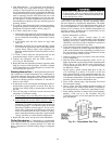
1. If the motor is equipped with space heaters, energize the
heaters to heat the winding.
50