


NOTE: If the chiller fails to stop, in addition to action that
the PIC initiates, the operator should close the guide vanes
by overriding the guide vane target to zero (to reduce chiller
load) and then by opening the main disconnect. Do not at-
tempt to stop the chiller by opening an isolating knife switch.
High intensity arcing may occur. Do not restart the chiller
until the problem is diagnosed and corrected.
After Limited Shutdown — No special preparations
should be necessary. Follow the regular preliminary checks
and starting procedures. Control power must be maintained
in order to keep the oil temperature hot and all control safe-
ties operational. The oil pump operates occasionally to keep
the contact seal filled with oil to prevent refrigerant loss.
Extended Shutdown — The refrigerant should be trans-
ferred into the economizer/storage vessel (see Pumpout and
Refrigerant Transfer Procedures, this page) in order to re-
duce chiller pressure and the possibility of leaks. Maintain
a holding charge of 5 to 10 lbs (2.27 to 4.5 kg) of refrigerant
within the cooler/condenser/compressor sections, to prevent
air from leaking into the chiller.
If freezing temperatures are likely to occur in the chiller
area, drain the chilled water, condenser water, and the pump-
out condenser water circuits to avoid freeze-up. Keep the
waterbox drains open.
Leave the oil charge in the chiller with the oil heater and
controls energized to maintain the minimum oil reservoir
temperature.
After Extended Shutdown — Be sure that the water
system drains are closed. It may be advisable to flush the
water circuits to remove any soft rust which may have formed.
This is a good time to brush the tubes if necessary.
Check the cooler pressure on the LID default screen, and
compare it to the original holding charge that was left in the
chiller. If (after adjusting for ambient temperature changes)
any loss in pressure is indicated, check for refrigerant leaks.
See the Check Chiller Tightness section, page 46.
Recharge the chiller by transferring refrigerant from
the economizer/storage vessel. Follow the Pumpout and Re-
frigerant Transfer Procedures section, this page. Observe
freeze-up precautions.
Carefully make all regular preliminary and running sys-
tem checks. Perform a controls test before start-up. If the
compressor oil level appears abnormally high, the oil may
have absorbed refrigerant. Make sure that the oil tempera-
ture is above 150 F (66 C) or above the cooler refrigerant
temperature plus 70° F (39° C).
Cold Weather Operation — When the entering con-
denser water temperature is very low, the PIC can automati-
cally cycle the cooling tower fans off to keep the tempera-
ture up. Provide a way to control the condenser water
temperature to the chiller either by arranging a tower bypass
piping system and/or adding a tower water temperature con-
trol system.
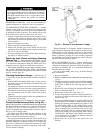
Manual Guide Vane Operation — It is possible to
operate the guide vane manually in order to check control
operations or control the guide vanes in an emergency. This
is done by overriding the target guide vane position. Access
the STATUS01 screen on the LID and highlight TARGET
GUIDE VANE POS. To control the position, enter the de-
sired percentage of guide vane opening. Zero percent is fully
closed; 100% is fully open. To release the guide vanes to
automatic operation, press the RELEASE
softkey.
NOTE: Manual guide vane control allows the operator to
manipulate the guide vane position and override the pull-
down rate during start-up. However, motor current above the
electrical demand setting, capacity overrides, and chilled wa-
ter temperature below the control point will override manual
guide vane control and close the guide vanes, if necessary.
For descriptions of capacity overrides and set points, see the
Controls section.
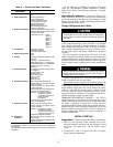
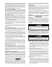
Refrigeration Log — A refrigeration log, such as the
one shown in Fig. 31, is a convenient way to track routine
inspection and maintenance and provides a continuous record
of chiller performance. It is an aid in scheduling routine main-
tenance and in diagnosing chiller problems.
Keep a record of the chiller pressures, temperatures, and
liquid levels on a log similar to Fig. 31. It is possible to au-
tomatically record PIC data by using CCN devices such as
the Data Collection module and a Building Supervisor ter-
minal. Contact your Carrier representative for more
information.
PUMPOUT AND REFRIGERANT TRANSFER
PROCEDURES
Preparation —
The 17EX may come equipped with
an optional pumpout compressor. The refrigerant can be pumped
for service work to either the cooler/condenser/compressor
sections or the economizer/storage vessel by using the pump-
out system. The following procedures describe how to trans-
fer refrigerant from vessel to vessel and perform chiller
evacuations.
To prevent tube freeze-up, always be sure that the con-
denser and cooler water pumps are operating whenever
charging, transferring, or removing refrigerant from the
chiller.
If the chiller water pumps are controlled by the PIC, ac-
cess the CONTROL TEST table on the LID and use the
PUMPDOWN/LOCKOUT screen or TERMINATE LOCK-
OUT screen to perform the functions described below. If the
chiller water pumps are not controlled by the PIC, they must
be turned on and off manually.
When performing pumpout, do not leave the compres-
sor unattended for long periods of time or loss of com-
pressor oil may result. Periodically check oil level.
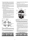
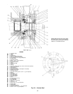
Operating the Optional Pumpout Compressor
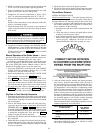
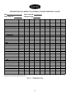
1. Be sure that the suction and the discharge service valves
on the optional pumpout compressor are open (back seated)
during operation. Figure 32 shows the location of these
valves (valves 2, 3, 4, 5, and 8). Rotate the valve stem
fully counterclockwise to open. Front seating the valve
closes the refrigerant line and opens the gage port to com-
pressor pressure.
2. Make sure that the compressor holddown bolts have been
loosened to allow free spring travel.
3. Open the refrigerant inlet valve on the pumpout compressor.
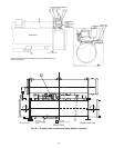
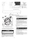
4. Oil should be visible in the compressor sight glass under
all operating conditions and during shutdown. If oil is
low, add oil as described under Pumpout System Main-
tenance section, page 83. The pumpout unit control wir-
ing schematic is detailed in Fig. 33. The Optional Pump-
out System is detailed in Fig. 34.
READING REFRIGERANT PRESSURES during pumpout
or leak testing:
1. The LID display on the chiller control center is suitable
for determining refrigerant-side pressures and low (soft)
vacuum. To measure evacuation or dehydration pres-
sures, use a quality vacuum indicator or manometer to
ensure the desired range and accuracy. This can be placed
on the Schrader connections on each vessel by removing
the pressure transducer.
63