


Control Modules
Turn the controller power off before servicing the con-
trols. This ensures safety and prevents damage to the
controller.
The Processor/Sensor Input/Output module (PSIO), 8-input
(Options) modules, Starter Management Module (SMM),
4-in/2-out module, and the Local Interface Device (LID) mod-
ule perform continuous diagnostic evaluations of the hard-
ware to determine its condition. Proper operation of all modules
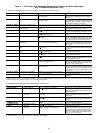
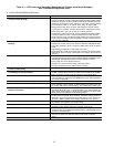
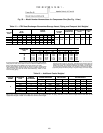
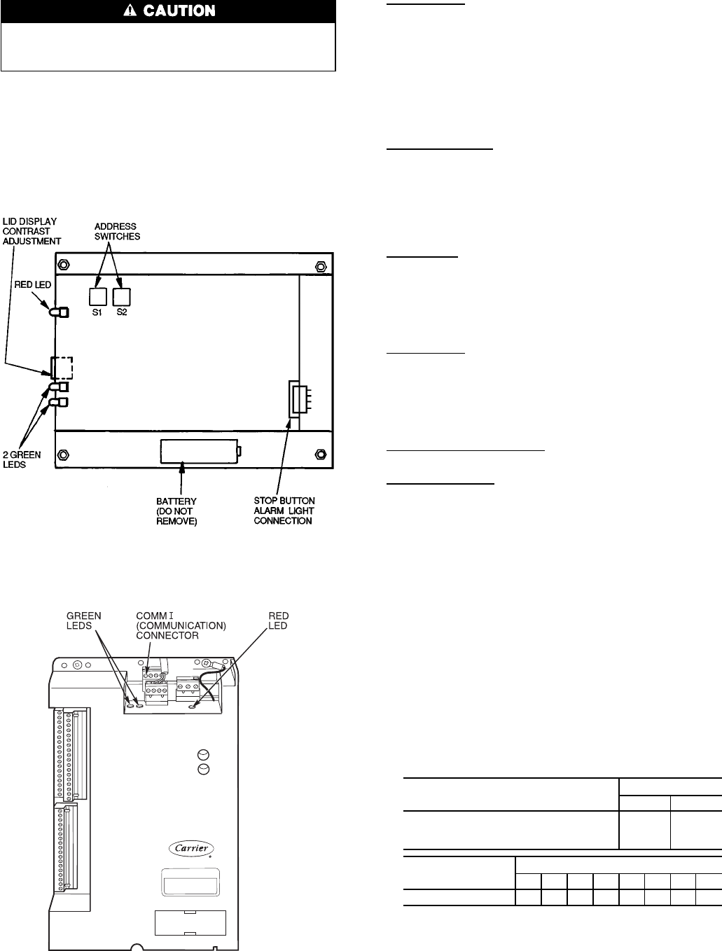
is indicated by LEDs (light-emitting diodes) located on the
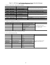
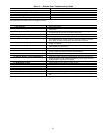
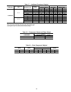
side of the LID (Fig. 49); on the top horizontal surface of the
PSIO (Fig. 50), SMM, and 8-input modules; and on the 4-in/
2-out module.
RED LEDs
PSIO Module — If the LED is blinking continuously at a
2-second rate, it is indicating proper operation. If it is lit con-
tinuously it indicates a problem requiring replacement of the
module. Off continuously indicates that the power should be
checked. If the red LED blinks 3 times per second, a soft-
ware error has been discovered and the module must be re-
placed. If there is no input power, check the fuses and the
circuit breaker. If the fuses are good, check for a shorted
secondary of transformer, or if power is present to the mod-
ule, replace the module.
4-In/2-Out Module — If the LED is blinking, this module is
operating properly.Asteady red light indicates a module fail-
ure. Replace the 4-In/2-Out module.
GREEN LEDs — There are 1 or 2 green LEDs on each type
of module. These LEDs indicate communication status be-
tween different parts of the controller and the network mod-
ules as follows:
LID Module
Upper LED — Communication with CCN network, if present;
blinks when communication occurs.
Lower LED — Communication with PSIO module; must blink
every 5 to 8 seconds when the LID default screen is
displayed.
PSIO Module
Green LED Closest to Communications Connection — Com-
munication with SMM and 8-input module; must blink
continuously.
Other Green LED — Communication with LID; must blink
every 3 to 5 seconds.
8-Input Modules and SMM — Communication with PSIO
module; blinks continuously.
4-In/2-Out Module — Communication with PSIO module;
blinks continuously.
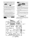
Notes on Module Operation
1. The chiller operator monitors and modifies configura-
tions in the microprocessor through the 4 softkeys and
the LID. Communication with the LID and the PSIO is
accomplished through the CCN bus (COMM1). The com-
munication between the PSIO, SMM, both 8-input mod-
ules, and the 4-in/2-out module is accomplished through
the sensor bus (COMM3), which is a 3-wire cable. On
the sensor bus terminal strips, Terminal 1 of the PSIO
module is connected to Terminal 1 of each of the other
modules. Terminals 2 and 3 are connected in the same
manner, except for the connection to the 4-in/2-out mod-
ule. See Fig. 51.
2. If a green LED is on continuously, check the communi-
cation wiring. If a green LED is off, check the red LED
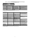
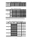
operation. If the red LED is normal, check the module
address switches (Fig. 52-54). Proper addresses are set as
shown below:
MODULE
ADDRESS
S1 S2
SMM (Starter Management Module) 32
8-input Options Module 1 64
8-input Options Module 2 72
MODULE
SWITCH
12345678
4-In/2-Out Module OOOOCOCO
O—Open
C—Closed
NOTE: Address switches on this module can be at any position. Ad-
dresses are only changed through the LID screen for CCN.
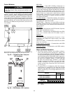
Fig. 49 — LID Module (Rear View) and
LED Locations
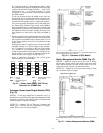
Fig. 50 — PSIO Module LED Locations
96