


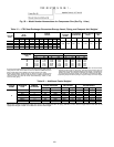
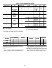
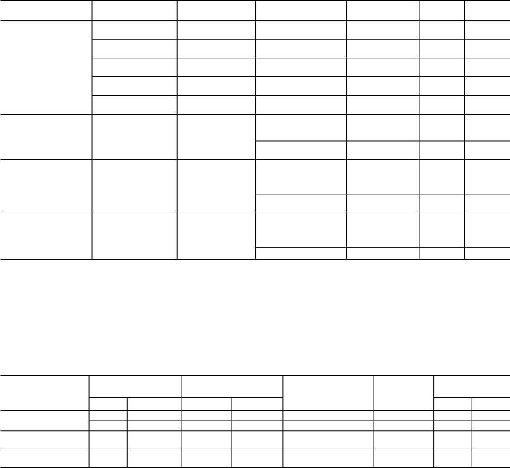
Table 24 — Auxiliary Systems, Electrical Data
POWER SOURCE ITEM AVERAGE kW
DESIGN CENTER
VOLTAGE
SUPPLY
V-PH-Hz
FLA LRA
1
Seal Leakage
Pump
0.23 115 115-1-50/60 4.78 21.7
Motor Space
Heater
0.50 115 115-1-50/60 4.35 4.35
Control Module
and Actuator
0.40 115
115-1-60
3.50 —
115-1-50
Oil Sump Heater 1.00 115
115-1-60
8.70 —
115-1-50
Hot Gas*
Bypass
0.20 115 115-1-50/60 2.00 4.75
2†
Compressor
Oil Pump
0.66
220 200/240-3-60 4.34 24.5
430 380/480-3-60 2.15 13.1
563 507/619-3-60 2.14 25.0
230 220/240-3-50 4.84 28.0
393 346/440-3-50 2.59 12.2
3†
Gear
Oil Pump
0.7
204 200/208-3-60 5.7 33.5
220 208/230-3-60 4.2 30.6
460 440/480-3-60 2.1 15.3
575 518/632-3-60 1.7 12.3
205 190/220-3-50 5.0 28.9
410 380/440-3-50 2.5 14.5
4
Pumpout*
Compressor
3.41
204 200/208-3-60 10.90 63.5
230 220/240-3-60 9.50 57.5
460 440/480-3-60 4.70 28.8
575 550/600-3-60 3.80 23.0
400 380/415-3-50 4.70 28.8
LEGEND
FLA — Full Load Amps
LRA — Locked Rotor Amps
*Available as an option on 17EX chillers.
†The compressor and gear oil pump contactors are wired together
on the line side. Their amperage values must be added together
when sizing conductors.
NOTE: The oil pump is powered through a field wiring terminal into
the power panel. Power to the controls and oil heater via the power
panel must be on circuits that can provide continuous service when
the compressor starter is disconnected.
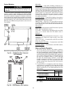
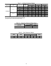
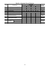
Table 25 — Relief Valve Locations and Data
RELIEF VALVE
LOCATION
HEAT EXCHANGER
SIZE
REQUIRED
C FACTOR
NOMINAL
OUTLET
PIPE SIZE
(in.)
NUMBER OF
VALVES
RATED RELIEF
PRESSURE
Cooler Condenser lb air/min. kg air/sec. psig kPa
Cooler
45-47 45-47 216.3 1.64 1
1
⁄
4
FPT 3 225 1551
48 55-57 228.5 1.73 1
1
⁄
4
NPT 3 225 1551
Economizer/Storage
Vessel
ALL ALL 84.3 0.64 1
1
⁄
4
FPT 2* 225 1551
Pumpout Unit
Condenser
ALL ALL 1.5 0.01
3
⁄
8
in. Male Flare MPT 1 385 2655
*To ensure relief valve serviceability, and as required inASHRAE 15,
latest edition, three-way valves and redundant relief valves are in-
stalled on the storage vessel. Only one of the ‘‘No. of Valves’’ listed
are in service at any time.
NOTES:
1. The cooler relief C-factor is for both cooler and condenser vented
through the cooler in accordance with ASHRAE (American
Society of Heating, Refrigeration, and Air Conditioning Engi-
neers) 15, latest edition.
2. Relief valve discharge pipe sizing is to be calculated per latest
version of ASHRAE 15, using the tabulated C-factors and nom-
inal pipe size listedabove. Cooler and economizer/storage vessel
rated relief valve pressure is 225 psig (1551 kPa).
3. The pumpout unit condenser contains less than 110 lb (50 kg) of
HFC-134a, whichisa GroupA1refrigerant.TheASHRAE15 stand-
ard exempts small-volume vessels from the requirement to vent
outside. However, Carrier recommends that the pumpout con-
denser be connected to the rest of the vent system.
104