


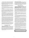
PROCESSOR/SENSOR INPUT/OUTPUT MODULE (PSIO)
— This module contains all the operating software needed
to control the chiller. The 17EX uses 5 pressure transducers
and 8 thermistors to sense pressures and temperatures. These
inputs are connected to the PSIO module. The PSIO also
provides outputs to the guide vane actuator, compressor and
gear oil pumps, oil heater, hot gas bypass (optional), and alarm
contact. The PSIO communicates with the LID, the SMM,
and the optional 8-input modules for user interface and starter
management.
STARTER MANAGEMENT MODULE (SMM) — This mod-
ule is located within the starter cabinet. This module ini-
tiates PSIO commands for starter functions such as start/
stop of the compressor; start/stop of the condenser and chilled
water pumps; start/stop of the tower fan, spare alarm con-
tacts, and the shunt trip. The SMM monitors starter inputs
such as flow switches, line voltage, remote start contact, spare
safety, condenser high pressure, oil pump interlock, motor
current signal, starter 1M and run contacts, and the kW trans-
ducer input (optional). The SMM contains logic capable of
safely shutting down the chiller if communication with
the PSIO is lost.
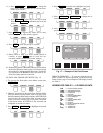
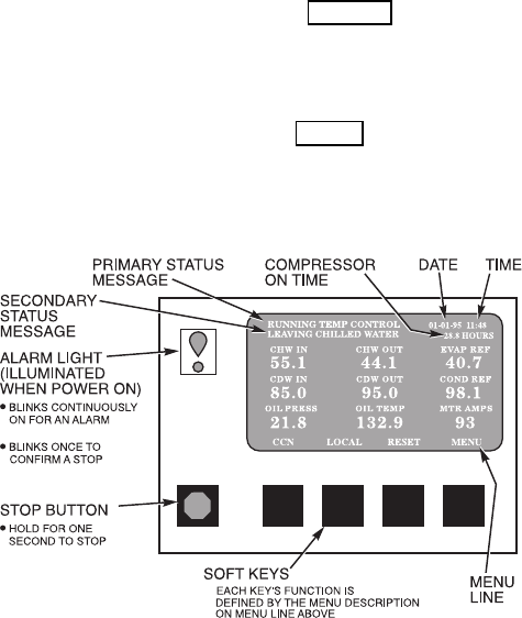
LOCALINTERFACE DEVICE (LID) — The LID is mounted
to the control center and allows the operator to interface with
the PSIO or other CCN devices. It is the input center for all
local chiller set points, schedules, set-up functions, and op-
tions. The LID has a STOP button, an alarm light, 4 buttons
for logic inputs, and a display. The function of the 4 buttons
or ‘‘softkeys’’are menu driven and are shown on the display
directly above the key.
SIX-PACK RELAY BOARD (6-Pack Relay Board) — This
device is a cluster of 6 pilot relays located in the control
center. It is energized by the PSIO for the compressor oil
pump, oil heater, alarm, optional hot gas bypass relay, aux-
iliary oil pump.
EIGHT-INPUT (8-Input) MODULES — One optional mod-
ule is factory installed in the control center panel when or-
dered. There can be up to 2 of these modules per chiller with
8 spare inputs each. They are used whenever chilled water
reset, demand reset, or reading a spare sensor is required.
The sensors or 4 to 20 mA signals are field-installed.
The spare temperature sensors must have the same
temperature/resistance curve as the other temperature sen-
sors on this unit. These sensors are rated 5,000 ohm at 75 F
(25 C).
FOUR-IN/TWO-OUT (4-IN/2-OUT) MODULE — This mod-
ule monitors and controls the external gear lubrication sys-
tem. It energizes the gear oil pump and is located in the power
panel.
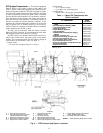
OIL HEATER CONTACTOR (1C) — This contactor is lo-
cated in the power panel and operates the heater at 115 v. It
is controlled by the PIC to maintain oil temperature during
chiller shutdown.
COMPRESSOR OILPUMP CONTACTOR (2C)AND GEAR
OIL PUMP CONTACTOR (5C) — These contactors are lo-
cated in the power panel. They operate all 200 to 575-v oil
pumps. The PIC energizes the contactor to turn on the oil
pumps as necessary.
HOT GAS BYPASS CONTACTOR RELAY (3C)
(Optional) — This relay, located in the power panel, con-
trols the opening of the hot gas bypass valve. The PIC en-
ergizes the relay during low load, high lift conditions.
OIL AUXILIARY RELAY (4C) — This relay opens the oil
cooler solenoid valve and interlocks the oil pump with the
compressor (special order).
CONTROL TRANSFORMERS (T1-T4) — These trans-
formers are located in the power panel and convert
incoming control voltage to either 21 vac power for the PSIO
module and options modules, or 24 vac power for 3 power
panel contactor relays and a control solenoid valve.
CONTROL AND OIL HEATER VOLTAGE SELECTOR
(S1) — It is necessary to use 115 v incoming control power
in the power panel. The switch must be set to the 115-v
position.
OIL DIFFERENTIAL PRESSURE/POWER SUPPLY
MODULE — This module, which is located in the control
center, provides 5 vdc power for the transducers and LID
backlight. This module outputs the difference between two
pressure transducer input signals. The module subtracts oil
supply pressure from transmission sump pressure and out-
puts the difference as an oil differential pressure signal to the
PSIO. The PSIO converts this signal to differential oil pres-
sure. To calibrate this reading, refer to the Troubleshooting,
Checking Pressure Transducers section on page 84.
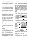
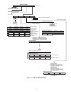
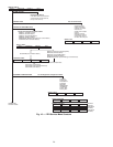
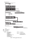
LID Operation and Menus (Fig. 11-17)
GENERAL
• The LID display automatically reverts to the default screen
(Fig. 11) after 15 minutes if no softkey activity takes place
and if the chiller is not in PUMPDOWN mode
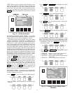
• When not displaying the default screen, the upper right-
hand corner of the LID displays the name of the screen
that you have entered (Fig. 12).
• The LID may be configured in English or SI units, through
the LID configuration screen.
• Local Operation — Pressing the LOCAL
softkey places
the PIC in LOCAL operation mode, and the control ac-
cepts modification to programming from the LID only. The
PIC uses the Local Time Schedule to determine chiller start
and stop times.
• CCN Operation — Pressing the CCN softkey places the
PIC in the CCN operation mode, and the control accepts
modifications from any CCN interface or module (with the
proper authority), as well as the LID. The PIC uses the
CCN time schedule to determine start and stop times.
ALARMS AND ALERTS — An alarm (*) or alert (!) status
is indicated on the default screen and the status tables. An
alarm (*) shuts down the compressor. An alert (!) notifies
the operator that an unusual condition has occurred. The chiller
continues to operate when an alert is shown.
Alarms are indicated when the control center alarm light
(!) flashes. The primary alarm message is viewed on the de-
fault screen and an additional, secondary, message and
troubleshooting information are sent to the ALARM HIS-
TORY table.
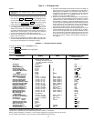
Fig. 11 — LID Default Screen
16