


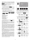
Safety Shutdown — A safety shutdown is identical to
a manual shutdown with the exception that the LID displays
the reason for the shutdown, the alarm light blinks continu-
ously, and the spare alarm contacts are energized. A safety
shutdown requires that the RESET
softkey be pressed in
order to clear the alarm. If the alarm continues, the alarm
light continues to blink. Once the alarm is cleared, the op-
erator must press the CCN
or LOCAL softkeys to restart
the chiller.
Do not reset starter loads or any other starter safety for
30 seconds after the compressor has stopped. Voltage
output to the compressor start signal is maintained for
10 seconds to determine starter fault.
BEFORE INITIAL START-UP
Job Data Required
• list of applicable design temperatures and pressures (prod-
uct data submittal)
• certified drawings of the chiller
• starting equipment details and wiring diagrams
• diagrams and instructions for special controls or options
• installation instructions
• pumpout unit instructions
Equipment Required
• mechanic’s tools (refrigeration)
• digital volt-ohmmeter (DVM)
• clamp-on ammeter
• electronic leak detector
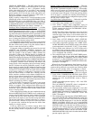
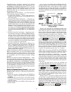
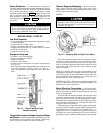
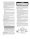
• absolute pressure manometer or wet-bulb vacuum indica-
tor (Fig. 23)
• 500 v insulation tester (megohmmeter) for compressor mo-
tors with nameplate voltage of 600 v or less, or a
5000 v insulation tester for compressor motor rated above
600 v
Using the Economizer/Storage Vessel and Pump-
out System —
Refer to the Pumpout and Refrigerant Trans-
fer Procedures section, page 63 for: pumpout system prepa-
ration, refrigerant transfer, and chiller evacuation.
Remove Shipping Packaging — Remove any pack-
aging material from the control center, power panel, guide
vane actuator, motor and bearing temperature sensor covers,
and the factory-mounted starter.
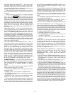
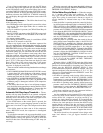
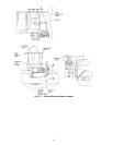
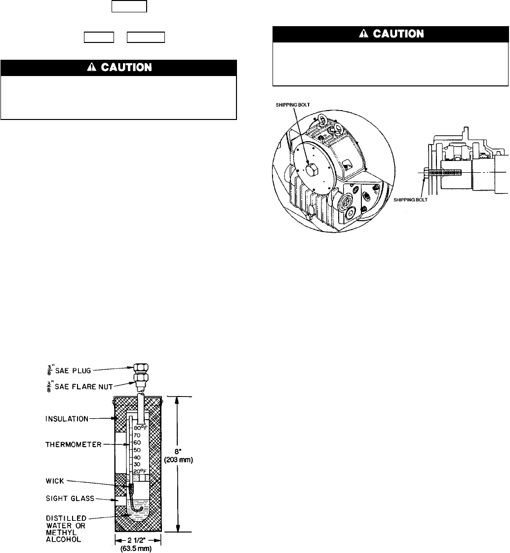
MOTOR
The motor may be provided with a shipping brace or
shipping bolt (normally painted yellow) to prevent shaft
movement during transit. It must be removed prior to
operation. See Fig. 24.
The motor should be inspected for any temporary, yellow
caution tags with legends that convey information concern-
ing actions necessary before the motor can be safely oper-
ated.Any slushing compound on the shaft or other parts must
be removed using a petroleum type solvent. Observe proper
safety precautions.
NOTE: If a shipping bolt was used to restrain the rotor, the
Westinghouse logo must be installed over the hole in the end-
cover. The logo, the gasket, and hardware can be found with
the parts that have been shipped loose. (Usually these are
packed inside the main power lead box.)
EXTERNAL GEAR — Remove any packaging material that
may be on the external gear. Be sure that the breather is in
place and free of any obstructions.
Motor Electrical Connection — All interconnect-
ing wiring for controls and grounding should be in strict com-
pliance with both the (NEC) National Electrical Code and
any local requirements.
The main lead box furnished with the motor has been sized
to provide adequate space for making up connections be-
tween the motor lead cables and the incoming power cables.
The bolted joints between the motor lead and the power cables
must be made and insulated in a workman-like manner fol-
lowing the best trade practices.
Fabricated motors are provided with 2 stainless steel ground-
ing pads drilled and tapped with the NEMA (National Elec-
trical Manufacturers Association) 2-hole pattern (two
1
⁄
2
-13
tapped holes on 1
3
⁄
4
in. centers). Fan cooled cast frames are
provided with a special grounding bolt. The motor should be
grounded by a proper connection to the electrical system ground.
Fig. 24 — Shipping Bolt on Open Drive Motor
Fig. 23 — Typical Wet-Bulb Type
Vacuum Indicator
45