


Refrigerant HFC-134a MUST NOT be mixed with air
or oxygen and pressurized for leak testing. In general,
this refrigerant should not be allowed to be present
with high concentrations of air or oxygen above atmo-
spheric pressures, because the mixture can undergo
combustion.
REFRIGERANT TRACER — Use an environmentally ac-
ceptable refrigerant as a tracer for leak test procedures.
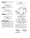
TO PRESSURIZE WITH DRY NITROGEN — Another
method of leak testing is to pressurize with nitrogen only
and use a soap bubble solution or an ultrasonic leak detector
to determine if leaks are present. This should only be done
if all refrigerant has been evacuated from the vessel.
1. Connect a copper tube from the pressure regulator on the
cylinder to the refrigerant charging valve. Never apply
full cylinder pressure to the pressurizing line. Follow the
listed sequence.
2. Open the charging valve fully.
3. Slowly open the cylinder regulating valve.
4. Observe the pressure gage on the chiller and close the
regulating valve when the pressure reaches test level. Do
not exceed 140 psi (965 kPa).
5. Close the charging valve on the chiller. Remove the cop-
per tube if no longer required.
Repair the Leak, Retest, and Apply Standing
Vacuum Test —
After pressurizing the chiller, test for
leaks with an electronic leak detector, soap bubble solution,
or an ultrasonic leak detector. Bring the chiller back to at-
mospheric pressure, repair any leaks found, and retest.
After retesting and finding no leaks, apply a standing vacuum
test, and then dehydrate the chiller. Refer to the Standing
Vacuum Test and Chiller Dehydration in the Before Initial
Start-Up section, page 49.
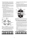
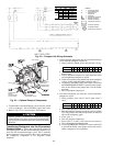
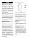
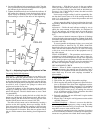
Checking Guide Vane Linkage — Refer to Fig. 35.
If slack develops in the drive chain, eliminate backlash as
follows:
1. With the chiller shut down (guide vanes closed), remove
the chain guard, loosen the actuator holddown bolts, and
remove the chain.
2. Loosen the vane sprocket set screw and rotate the sprocket
wheel until the set screw clears the existing spotting hole.
3. With the set screw still loose, replace the chain, and move
the vane actuator to the left until all the chain slack is
taken up.
4. Tighten the actuator holddown bolts and retighten the set
screw in the new position.
5. Realign the chain guard as required to clear the chain.
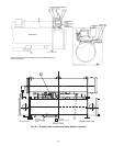
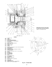
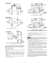
Contact Seal Maintenance (Refer to Fig. 36) —
During chiller operation, oil that lubricates the seal seeps through
the space between the contact sleeve (Item 18) and the lock
nut (Item 15). This oil slowly accumulates in an atmo-
spheric oil chamber and is automatically returned to the sys-
tem by a seal oil return pump.
Oil should never leak around the outer diameter of the
contact sleeve (Item 18). If oil is found in this area, O-ring
(Item 12) should be checked and replaced.
The oil passing through the shaft seal carries with it some
absorbed refrigerant. As the oil reaches the atmosphere, the
absorbed refrigerant is released from the oil as a vapor. For
this reason, a detector will indicate the presence of a slight
amount of refrigerant around the compressor shaft when-
ever the chiller is running.
During shutdown, no refrigerant should be detected ex-
cept for minute outgassing from residual oil in the seal area.
There should be no oil seepage. If oil flow or the presence
of refrigerant is noted while the chiller is shut down, a seal
defect is indicated. Arrange for a seal assembly inspection
by a qualified serviceman to determine the cause of the leak-
age and make the necessary repairs.
SEAL DISASSEMBLY (Fig. 36) — Contact seal disassem-
bly and repair should be performed only by well qualified
compressor maintenance personnel. These disassembly in-
structions are included only as a convenient reference for
the authorized serviceman.
For ease of disassembly, refer to Fig. 36 while following
these instructions.
1. Remove refrigerant.
2. Remove compressor shaftcoupling hub and coupling spacer
(if any).
3. The snap ring (Item 16) used for seal assembly/disassembly
is clipped over three screws (Item 41) on the windage
baffle (Item 7). Remove the snap ring and put it aside
for now.
4. Remove the screws holding the windage baffle and the
shaft end labyrinth (Item 8).
5. Remove the contact sleeve key (Item 11).
6. Using a snap ring tool, install the snap ring (Item 16) in
the groove on the end of the contact sleeve (Item 18), as
shown in Fig. 36.
7. Remove the tubing between the coupling (Item 20) and
the atmospheric oil chamber. Loosen the bolts (Item 6)
holding the coupling guard mounting ring (Item 4) and
the seal housing (Item 3). The spring contact sleeve
(Item 17) will push the housing out until the snap ring
(Item 16) contacts the seal housing (Item 3). To avoid
binding, loosen the bolts in a circular pattern until the
spring stops pushing out on the housing. Then, remove
2 bolts that are 180 degrees apart. Replace them with a
1/2-13 all-thread rod to support the housing while the
rest of the bolts are removed.
8. Remove the rest of the bolts, and remove the seal
housing.
Fig. 35 — Electronic Vane Actuator Linkage
68