


The lubricant should be drained while the gear is at op-
erating temperature. The gear drive should be cleaned with
a flushing oil. Used lubricant and flushing oil should be com-
pletely removed from the system to avoid contaminating new
oil.
To change the oil in the external gear:
1. Make sure that the compressor is off and the disconnect
for the compressor is open.
2. Disconnect the power to the oil heater, if equipped, and
the oil pump.
3. Open the drain located on the shell of the cooler/filter.
Run a hose from the drain to a bucket to catch the oil.
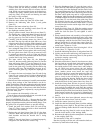
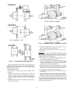
4. Once the pressure has been removed and the oil drained,
loosen the bolts that hold the cover on the filter body.
Remove the old filter cartridges. Assemble the filter as-
sembly (filters, spacer, and stopper assembly), and make
sure that the spring is centered against the filter assembly
as shown in Fig. 44.
5. Replace the drain fitting, using standard practices to en-
sure a leak-tight joint.
6. Open the isolation valves and add new oil. Refer to
Table 11 for oil specifications.
7. Connect power to the oil heater, if equipped, and the oil
pump. Operate the oil pump for 2 minutes. Add oil, if
required, to keep the level up in the sight glass.
MOTOR SLEEVE BEARING AND PUMPOUT COM-
PRESSOR OIL — For instructions on changing the motor
sleeve bearing oil, refer to the section on Motor Mainte-
nance, this page.
For instructions on changing the optional pumpout com-
pressor and oil separator oil, refer to the section on Pumpout
System Maintenance, page 83.
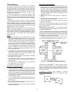
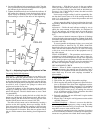
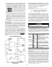
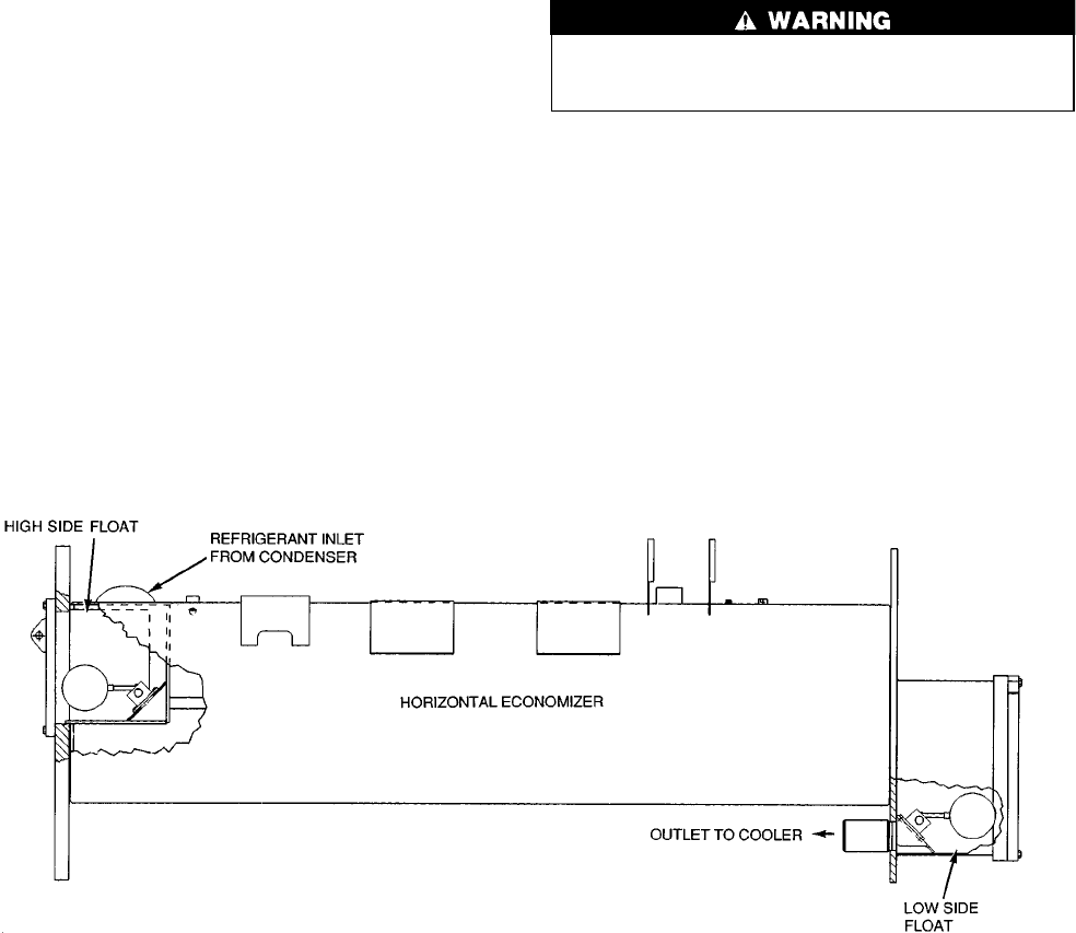
Inspect Refrigerant Float System — Inspect the
refrigerant float system once every 5 years or when the
economizer/storage vessel is opened for service. Transfer the
refrigerant into the cooler vessel or into a storage tank. There
are two floats on the 17EX, one on each side of the economizer/
storage vessel. Remove the float access covers. Clean the
chambers and valve assembly thoroughly. Be sure that the
valves move freely. Make sure that all openings are free of
obstructions. Examine the cover gaskets and replace if nec-
essary. See Fig. 45 for a view of both floats.
Inspect Relief Valves and Piping — The relief valves
on this chiller protect the system against the potentially dan-
gerous effects of overpressure. To ensure against damage to
the equipment and possible injury to personnel, these de-
vices must be kept in peak operating condition.
As a minimum, the following maintenance is required.
1. At least once a year, disconnect the vent piping at the
valve outlet and carefully inspect the valve body and mecha-
nism for any evidence of internal corrosion or rust, dirt,
scale, leakage, etc.
2. If corrosion or foreign material is found, do not attempt
to repair or recondition. Replace the valve.
3. If the chiller is installed in a corrosive atmosphere or the
relief valves are vented into a corrosive atmosphere, make
valve inspections at more frequent intervals.
Coupling Maintenance — Proper coupling mainte-
nance is important since the coupling supports the outboard
end of the compressor high speed shaft. Clean and inspect
both couplings for wear yearly. Misalignment causes undue
noise and wear. Check alignment yearly, or more often if
vibration or heating occur. Refer to Chiller Alignment sec-
tion, page 71.
Never operate the drive without the coupling guards in
place. Contact with a rotating shaft or coupling can cause
serious injury.
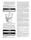
Motor Maintenance — A carefully planned and ex-
ecuted program of inspection and maintenance will do much
to ensure maximum motor availability and minimum main-
tenance cost. If it becomes necessary to repair, recondition,
or rebuild the motor, it is recommended that the nearest West-
inghouse repair facility be consulted.
In addition to a daily observation of the appearance and
operation of the motor, it is recommended that a general in-
spection procedure be established to periodically check the
following items:
• cleanliness, both external and internal
• stator and rotor (squirrel-cage) windings
• bearings
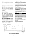
Fig. 45 — Typical Float Valve Arrangement
78