


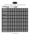
Table 8 — Control Test Menu Functions
TESTS TO BE DEVICES TESTED
PERFORMED
1. Automated Tests* Operates the second throughseventh
tests
2. PSIO Thermistors Entering chilled water
Leaving chilled water
Entering condenser water
Leaving condenser water
Discharge temperature
Bearing temperature
Motor winding temperature
Oil sump temperature
3. Options Thermistors Common chilled water supply sensor
Common chilled water return sensor
Remote reset sensor
Temperature sensor — Spare 1
Spare 2
Spare 3
Spare 4
Spare 5
Spare 6
Spare 7
Spare 8
Spare 9
4. Transducers Evaporator pressure
Condenser pressure
Oil pressure differential†
5. Guide Vane Actuator Open
Close
6. Pumps All pumps orindividual pumps may be
activated:
Oil pump — Confirm pressure
Chilled water pump — Confirm flow
Condenserwater pump—Confirm flow
Auxiliary oil pump — confirm
pressure†
7. Discrete Outputs All outputs or individual outputs may
be energized:
Hot gas bypass relay
Oil heater relay
Motor cooling relay
Tower fan relay
Alarm relay
Shunt trip relay
8. Pumpdown/Lockout When using pumpdown/lockout,
observe freeze up precautions when
removing charge.
Instructs operator as to which valves
to close and when.
Starts chilledwaterand condenserwa-
ter pumps and confirms flows.
Monitors — Evaporator pressure
Condenser pressure
Evaporator temperature
during pumpout
procedures
Turns pumps off after pumpdown.
Locks out compressor.
9. Terminate Lockout Starts pumps and monitors flows.
Instructs operator as to which valves
to open and when.
Monitors — Evaporator pressure
Condenser pressure
Evaporator temperature
during charging process
Terminates compressor lockout.
10. FX Gear Oil
Pump I/O
Activates gear main oil pump; con-
firms pressure.
Activates optionalgear auxiliarypump;
confirms pressure.
*During anyof the teststhat are notautomated, an out-of-rangeread-
ing will have an asterisk (*) next to the reading and a message will
be displayed.
†On open-drive chillers, differential pressure is the only oil pressure
displayed.
See the Pumpout and Refrigerant Transfer Procedures
(page 63) and Pumpout System Maintenance sections
(page 83) for details on transferring refrigerant, oil specifi-
cations, etc.
High Altitude Locations — Because the chiller is ini-
tially calibrated at sea level, it is necessary to recalibrate the
pressure transducers if the chiller is to be operated at a high
altitude location. Please see the calibration procedure in the
Troubleshooting Guide section.
Charge Refrigerant into Chiller
The transfer, addition, or removal of refrigerant in spring
isolated chillers may place severe stress on external pip-
ing if springs have not been blocked in both up and down
directions.
The 17EX chiller may have the refrigerant already charged
in the economizer/storage vessels. If chiller is not shipped
fully charged, refrigerant is shipped separately to conform
with transportation regulations. The 17EX may be ordered
with a nitrogen holding charge of 15 psig (103 kPa). Evacu-
ate the entire chiller, and charge chiller from refrigerant
cylinders.
The full refrigerant charge on the 17EX will vary with
chiller components and design conditions as indicated on the
job data specifications. An approximate charge may be found
in Physical Data and Wiring Schematics section, page 99.
The full chiller charge is printed on the chiller identification
label.
Always operate the condenser and chilled water pumps
during charging operations to prevent water in heat ex-
changer tubes from freezing.
Use the CONTROLS TEST terminate lockout function to
monitor conditions and start the pumps.
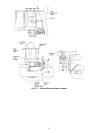
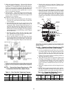
If the chiller has been shipped with a holding charge, add
refrigerant through the refrigerant charging valve (Fig. 6) or
to the pumpout charging connection. First evacuate the ni-
trogen holding charge from the vessels. Charge the refrig-
erant as a gas until the system pressure exceeds 35 psig
(141 kPa). After the chiller is beyond this pressure, the re-
frigerant should be charged as a liquid until all the recom-
mended refrigerant charge has been added.
TRIMMING REFRIGERANT CHARGE — The 17EX is
shipped with the correct charge for the design duty of the
chiller. Trimming the charge can best be accomplished when
the chiller is operating at design load. To trim, check the
temperature difference between the leaving chilled water tem-
perature and the cooler refrigerant temperature at full load
design conditions. If necessary, add or remove refrigerant to
bring the temperature difference to design conditions or a
minimum differential.
INITIAL START-UP
Preparation —
Before starting the chiller, check that the:
1. Power is on to the main starter, oil pump relay (which
energizes both the compressor and gear oil pumps), tower
fan starter, oil heater relay, and the chiller control
center.
2. Cooling tower water is at proper level and at or below
design entering temperature.
57