


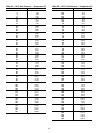
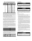
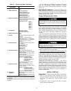
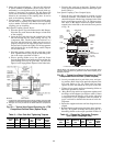

If surge prevention occurs too soon or too late, make the
following adjustments:
LOAD
SURGE PREVENTION SURGE PREVENTION
OCCURS TOO SOON OCCURS TOO LATE
At low loads
(Ͻ50%)
Increase P1 by
10 psid (70 kPad)
Decrease P1 by
10 psid (70 kPad)
At high loads
(Ͼ50%)
Increase P2 by
10 psid (70 kPad)
Decrease P2 by
10 psid (70 kPad)
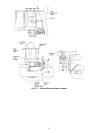
MODIFY EQUIPMENT CONFIGURATION IF NECES-
SARY — The EQUIPMENT CONFIGURATION table has
a number of screens to select, view, and/or modify. See
Fig. 16 for the menu structure of this table. Carrier provides
certified drawings that have the configuration values re-
quired for specific jobsites. Modify these values only if
requested.
CONFIG Screen Modifications — Change the values on this
screen according to your job data. See certified drawings for
the correct values. Modifications can include:
• chilled water reset
• entering chilled water control (Enable/Disable)
• 4 to 20 mA demand limit
• auto. restart option (Enable/Disable)
• remote contact option (Enable/Disable)
LEAD/LAG Screen Modifications — Change the values on
this screen according to your job data. See certified draw-
ings for specific values. Modifications can include:
• lead/lag selection
• load balance option
• common sensor option
• lag start/stop timers
• standby chiller option
Owner-Modified CCN Tables— The following tables are de-
scribed for reference only. For detailed information on CCN
operations, consult the CCN supplement for your chiller.
• OCCDEFCS Screen Modifications — This table contains
the local and CCN time schedules, which can be modified
here, or on the SCHEDULE screen as described
previously.
• HOLIDEF Screen Modifications — This table configures
the days of the year that holidays are in effect. See the
holiday paragraphs in the Controls section for more
details.
• BRODEF Screen Modifications — This table defines the
outside-air temperature sensor and humidity sensor if one
is to be installed. It also defines the start and end of day-
light savings time. Enter the dates for the start and end of
daylight savings, if required for your location. BRODEF
also activates the Broadcast function, which enables the
holiday periods defined on the LID to take effect.
• Other Tables — The ALARMDEF, CONS-DEF, RUNT-
DEF, and WSMALMDF screens contain information for
use with a CCN system. See the applicable CCN manual
for more information on these screens. These screens can
only be changed from a CCN Building Supervisor
terminal.
CHECK VOLTAGESUPPLY—Access the STATUS 01screen
and read the LINE VOLTAGE: ACTUAL value. This reading
should be equal to the incoming power to the starter. Use a
voltmeter to check incoming power at the starter power leads.
If the readings are not equal, an adjustment can be made by
selecting the LINE VOLTAGE: ACTUAL parameter and then
increasing or decreasing the value so that the value appear-
ing on the LID is calibrated to match the incoming power
voltage reading. Voltage can be calibrated only between 90
and 100% of the rated line voltage.
PERFORMAN AUTOMATED CONTROL TEST — Check
the safety controls status by performing an automated con-
trols test. Access the CONTROLTEST table from the SERV-
ICE menu. This table has the following screens:
Automated Test As described above, a complete
control test.
PSIO Thermistors Checks all PSIO thermistors only.
Options Thermistors Checks all options board thermistors.
Transducers Checks all transducers.
Guide Vane Actuator Checks the guide vane operation.
Pumps Checks operation of pump output;
either all pumps can be
activated or individual pumps.
Also tests the associated input
such as flow or pressure.
Discrete Outputs Activates all on/off outputs, all
at once or individually.
Pumpdown/Lockout Pumpdown prevents the low
refrigerant alarm during
evacuation so refrigerant
can be removed from the unit,
locks the compressor off. and
starts the water pumps.
Terminate Lockout Charges refrigerant and enables
the chiller to run after pumpdown
lockout.
FX Gear Oil Pump I/O Activates external gear main oil pump
and auxiliary oil pump (if supplied).
Automated Test — Before running this test, be sure that the
compressor is in the OFF mode and the 24-v input to the
SMM is in range (per line voltage percent on STATUS01
screen). Put the compressor in OFF mode by pressing the
STOP pushbutton on the LID.
The automated test starts with a check of the PSIO ther-
mistors and proceeds through the rest of the tests listed in
the table below. The test not only checks readings, such as
temperature and pressure readings, but also lets the operator
know if certain devices, such as pumps or relays, are on or
off and if all outputs and inputs are functioning. It also sets
the refrigerant type.
As each test is executed, the LID display shows which
test is running as well as other pertinent data. At the end of
each test, the LID displays, OK TO CONTINUE? If a test
indicates a problem, error, or device malfunction, the op-
erator can choose to address the problem as the test is being
done or note the problem and proceed to the next test.
NOTE: If during the control test the guide vanes do not open,
check to see that the low pressure alarm is not active. (This
causes the guide vanes to close.)
NOTE: The oil pump test will not energize the oil pump if
cooler pressure is below –5 psig (–35 kPa).
When the test is finished, or the EXIT
softkey is pressed,
the test stops and the CONTROL TEST menu is displayed.
If a specific automated test procedure is not completed, ac-
cess that test by scrolling to it and selecting it to test the
function when ready. The CONTROL TEST menu is de-
scribed in more detail in Table 8.
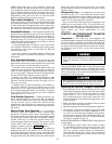
Check Pumpout System Controls and Optional
Pumpout Compressor —
The pumpout system con-
trols include an on/off switch, a 3-amp fuse, the compressor
overloads, an internal thermostat, a compressor contactor, and
a refrigerant high pressure cutout. The high pressure cutout
is factory set to open at 161 psig (1110 kPa) and reset at
130 psig (896 kPa). Check that the water-cooled condenser
has been connected. Loosen the compressor holddown bolts
to allow free spring travel. Open the compressor suction and
discharge service valves. Check that oil is visible in the com-
pressor sight glass. Add oil if necessary.
56