


If the larger opening remains the same but changes from
side to side, the shafts are in perfect alignment. The change
in opening is due entirely to coupling runout, as above, or to
a burr or other damage to the coupling face.
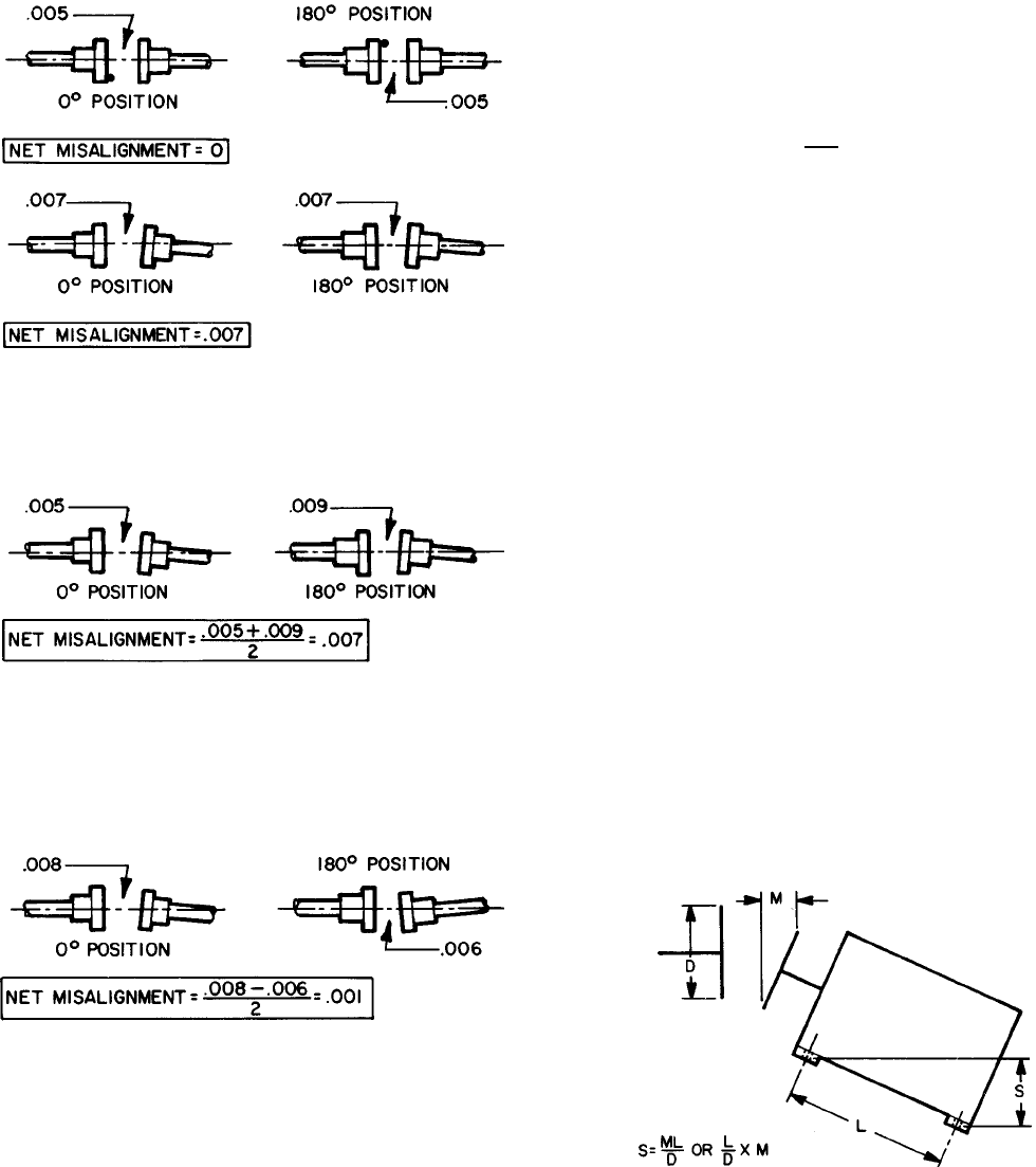
If the larger opening remains the same, and remains
on the same side, the amount is entirely shaft (net)
misalignment.
If the larger opening remains on the same side but changes
amount, misalignment and runout are present. Add the two
amounts and then divide by two to get the actual or net
misalignment.
If the larger opening changes amount and also changes
from side to side, subtract the smaller amount from the larger
and divide by two to obtain the net misalignment.
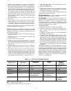
Adjustment — Having obtained the net misalignment, the
amount by which the equipment must be moved can now be
calculated.
To determine:
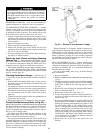
S — amount of movement (in plan) or the thickness of
shim (in elevation) required.
Obtain:
D — coupling face diameter in inches (or indicator but-
ton circle)
L — distance between front and rear holddown bolts
(inches)
M — net misalignment in inches
And:
Divide L, the bolt distance, by D, the coupling diameter.
Multiply the result by M, the net misalignment.
L
S= × M
D
Example: Face diameter 5 in. (D). Distance between front
and rear holddown bolts 30 in. (L). Net misalign-
ment in elevation .012 in. (M).
30 divided by 5 is 6
6 multiplied by .012 is .072 in.
S = .072 in.
If the larger opening between coupling faces is at the top,
place .072 in. of shim under each rear foot or remove
.072 in. from the front footings to bring the couplings into
angular alignment in elevation.
Tighten the holddown bolts and recheck the net
misalignment.
The height of the shaft above the footings and the dis-
tance the shaft extends beyond the equipment will not affect
the calculations.
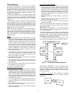
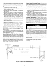
Determine the angular adjustment in plan by the same method
of calculation. At this point, however, the procedure should
include a correction for the change in coupling gap which
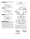
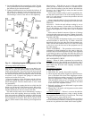
always occurs in adjusting angular alignment (Fig. 40). By
selecting the proper pivot point (see Fig. 41), the coupling
gap can be kept at the dimension specified in the job data.
1. Pivot on the front bolt at the closed side of the couplings
to shorten the gap; pivot on the front bolt at the open side
to lengthen it. It may sometimes be advantageous to pivot
half the required amount on one front footing and half on
the other.
2. Place a dial indicator against the rear foot as indicated in
Fig. 41.
3. Place a screw jack on the other rear foot to move the equip-
ment towards the indicator.
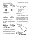
S—Thickness of Shim Required
L—Distance Between Front and
Rear Holddown Bolt in Inches
D—Diameter of Coupling in Inches
M—Net Misalignment in Inches
Fig. 40 — Alignment Formula
73