


3. Chiller is charged with refrigerant and all refrigerant and
all oil valves are in their proper operating position.
4. Gear oil, compressor oil, and motor bearing oil are at the
proper levels in the reservoir sight glasses.
5. Compressor oil reservoir temperature is above 140 F
(60 C) or refrigerant temperature plus 50° F (28° C).
6. Valves in the evaporator and condenser water circuits are
open.
NOTE: If the water pumps are not automatic, make sure
water is circulating properly.
7. Check the starter to be sure it is ready to start and that all
safety circuits have been reset. Be sure to keep the starter
door closed.
Do not permit water or brine that is warmer than 110 F
(43 C) to flow through the cooler or condenser. Refrig-
erant overpressure may discharge through the relief de-
vices and result in the loss of refrigerant charge.
8. To prevent accidental start-ups, the CHILLER START/
STOP parameter is set to STOP at the factory. Access the
STATUS01 screen and scroll to the CHILLER START/
STOP parameter. Press the RELEASE
softkey to enable
the chiller to start.
Manual Operation of the Guide Vanes — Manual
operation of the guide vanes helps to establish a steady mo-
tor current when calibrating the motor amps value.
To manually operate the guide vanes, override the target
guide vane position (TARGET GUIDE VANE POS param-
eter on the STATUS01 screen). Manual control is also in-
dicated on the default screen on the run status line.
1. Access the STATUS01 screen and look at the TARGET
GUIDE VANE POS parameter. (Refer to Fig. 13). If the
compressor is off, the value reads zero.
2. Move the highlight bar to the TARGET GUIDE VANE
POS parameter and press the SELECT
softkey.
3. Press ENTER
to override the automatic target. The screen
reads a value of zero. The word SUPVSR! flashes to in-
dicate that manual control is in effect. The default screen
also indicates that the guide vanes are in manual control.
4. To return the guide vanes to automatic mode, press the
SELECT
softkey; then press the RELEASE softkey.
After a few seconds, the word SUPVSR! disappears.
Dry Run to Test Start-Up Sequence
1. Disengage the main motor disconnect on the starter front
panel. This should only disconnect the motor power. Power
to the controls, oil pumps, and starter control circuit should
still be energized.
2. Look at the default screen on the LID. The status mes-
sage in the upper left corner should read, MANUALLY
STOPPED. Press the CCN or LOCAL softkey to start.
If MANUALLY STOPPED is not on the default screen
access the SCHEDULE screen and override the schedule
or change the occupied time. Then, press the LOCAL
softkey to begin the start-up sequence.
3. Check that the chilled water and condenser water pumps
have energized.
4. Check that the oil pumps have started and have pressur-
ized the lubrication system. After the oil pumps have run
about 15 seconds, the starter energizes and goes through
its start-up sequence.
5. Check the main contactor for proper operation.
6. The PIC will activate an alarm for motor amps not sensed.
Reset this alarm and continue with the initial start-up.
Check Motor Rotation
INITIAL MOTOR START-UP
Initial Uncoupled Start-Up — The initial start-up of the mo-
tor should be made with the motor uncoupled. Verify that oil
has been added to each bearing housing to the correct level.
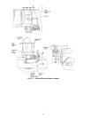
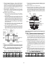
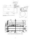
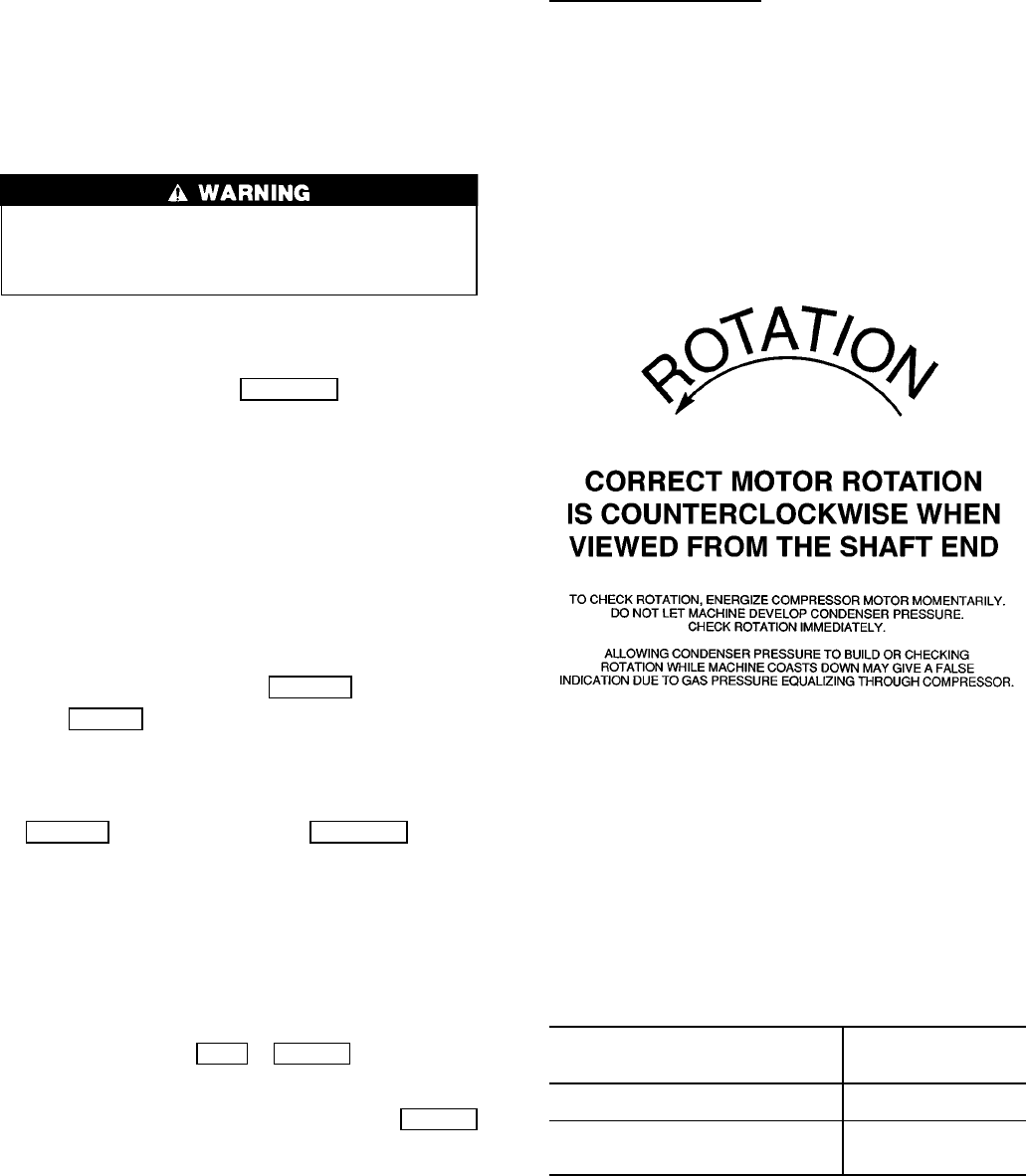
1. If the motor is equipped with unidirectional fans (refer to
the certified drawing) and verification of rotation direc-
tion is required, do the following:
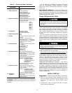
a. Start the motor and observe the rotation direction. See
Fig. 28.
b. Allow the motor to achieve full speed before discon-
necting it from the power source.
c. If the rotation direction must be changed, refer to the
Before Initial Start-Up, Motor Electrical Connection
section, page 45. Otherwise, the motor can be re-
started immediately after it has coasted to a stop.
2. After the initial start-up, monitor the bearing tempera-
tures closely. Verify the free rotation of the oil rings on
the sleeve bearings by observing them through the view-
ing port in the top of the housing. The rate of rise in bear-
ing temperature is more indicative of impending trouble
than the actual temperature. If the rate of rise in tempera-
ture is excessive or if the motor exhibits excessive vi-
bration or noise, shut it down immediately and conduct a
thorough investigation to find the cause before operating
the motor again. If the bearing temperatures rise and mo-
tor operation appears to be normal, continue operating
the motor until the bearing temperatures stabilize.
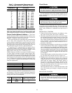
The recommended limits on bearing temperature rise over
ambient temperature are listed below:
Sleeve Bearing Temperature
As Measured By
Temperature Rise
Over Ambient
Temperature
A permanently installed
detector
72° F (40° C)
A temporary detector on top
of the bearing sleeve near the
oil ring
63° F (35° C)
NOTE: When operating flood-lubricated sleeve bearings,
the bearing temperature must not be allowed to exceed
185 F (85 C) total temperature.
Fig. 28 — Correct Motor Rotation
58