


2. Offset and Angular Alignment — Reverse dial indication
or optical methods of alignment (such as lasers) are rec-
ommended. A cold alignment and a hot check (with cor-
rections, if necessary) are required. The hub flange OD
can be used to mount the alignment equipment and is ma-
chined to be concentric to the coupling bore. It can be
used as the reference diameter.
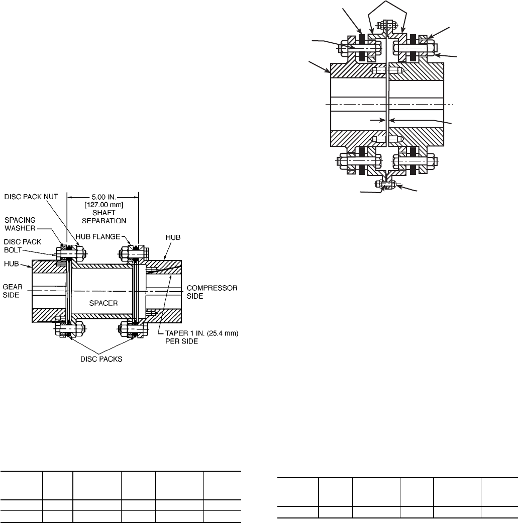
3. Final Assembly — The terminology used to identify parts
and the order of assembly may differ from one coupling
style to another. Follow the instructions that apply to the
coupling you are installing.
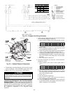
High Speed Coupling (Spacer Style):
a. Place the spacer in position between the hub flanges.
Place the disc packs between the flanges on both ends
of the coupling.
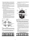
b. Insert the disc pack bolt into the reamed hole of the
hub and through the disc pack bushing. See Fig. 29
(compressor side). The flat of the bolt head acts as a
bolt lock with the hub body. Make sure the spacer is
properly indexed for the large flange holes to receive
the bolt ends. Tap the bolts lightly for full engagement
until the heads rest on the hub flange surface. Repeat
for the other bolts.
c. Place the spacing washers and disc pack nuts on the
bolts. Tighten all nuts evenly and in an alternating fash-
ion to the torque specified in Table 9.
d. Place a spacing washer over a disc pack bolt. Insert
the bolt through the large hub flange hole and the disc
pack bushing. See Fig. 29 (gear side). Tap the bolts
lightly for full engagement. Repeat for the other bolts.
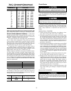
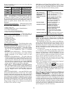
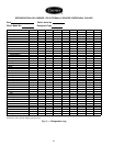
Table 9 — Disc Pack Nut Tightening Torques
Coupling
Size
Nut
Size
Tightening
ft-lb
Torque
(dry)
N-m
Tightening
ft-lb
Torque
(lubed)*
N-M
204 1/2-20 55 75 45 60
304 5/8-18 115 155 90 120
*Light machine oil.
e. Place the disc pack nuts on the bolts. Tighten all nuts
evenly and in an alternating fashion to the torque speci-
fied in Table 9.
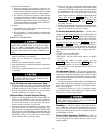
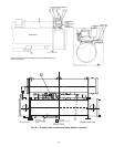
Low Speed Coupling (Close-Coupled Style):
a. Place the disc pack and adapter in position over the
hub body diameter. The reamed holes in the adapter
should be aligned with the large clearance holes in the
hub as in the upper portion of Fig. 30. The large clear-
ance holes in the adapter should be aligned with the
reamed holes in the hub as shown in the lower portion
of Fig. 30.
b. Loosely assemble the disc pack bolts, nuts, and spac-
ing washers. Half of the bolts attach the adapter to the
disc pack. Refer to Fig. 30. These bolts are inter-
spersed by bolts that attach the disc pack to the hub.
c. Tighten all nuts evenly and in an alternating fashion to
the torque specified in Table 9.
d. Bring the driving and driven equipment together until
the flanges of the adapters just begin to touch. If there
is a gap between the flanges at any point, adjust the
axial position of the equipment until the amount of
gap is cut in half to minimize the amount of axial mis-
alignment.
e. Rotate the equipment shafts until the flange holes are
aligned.
f. Bolt the flanges together using the flange bolts and nuts.
See Fig. 30. Tighten all flange nuts evenly and in a
alternating fashion to the torque specified in Table 10.
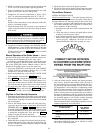
Table 10 — Flange Nut Tightening Torques
(Low Speed Couplings Only)
Coupling
Size
Nut
Size
Tightening
ft-lb
Torque
(dry)
N-m
Tightening
ft-lb
Torque
(lubed)*
N-M
304 5/16-24 20 27 18 24
*Light machine oil.
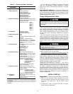
NOTES:
1. Compressor shaft should be in the thrust position and gear shaft
shouldbe ongeometriccenter whencouplingispositioned asshown.
2. The taper is 1 inch per side for the driven unit bore (compressor
side).
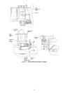
Fig. 29 — Typical High Speed Coupling for 17FX
Compressor/External Gear (Spacer Style)
SHAFT
PREPARATION
(0.19 IN.
[4.83 mm]
GEAR
SIDE
DISC
PACK
NUT
SPACING
WASHER
ADAPTERSDISK
PACK
DISC
PACK
BOLT
HUB
MOTOR
SIDE
FLANGE BOLT FLANGE NUT
NOTE: Motor rotor should be positioned on the mechanical center
and gear shaft should be on geometric center when coupling is po-
sitioned as shown.
Fig. 30 — Typical Low Speed Coupling for 17FX
Compressor/External Gear (Close Coupled)
60