


4. General Recommendations
a. Both disc couplings are designed to operate for ex-
tended periods without the need for lubrication or main-
tenance. Visual inspection of the disc packs is enough
to assess the operational condition of the coupling.
b. All machinery should be monitored to detect unusual
or changing vibration levels. Both couplings, under nor-
mal operating conditions, have no wearing parts and
retain their original balance quality.Any change in vi-
bration levels should be investigated, and remedial ac-
tion should be taken immediately.
5. Removal
a. Disassemble the coupling in the reverse order of the
applicable assembly procedure.
b. Keyed couplings — Install a puller on the hub using
the tapped holes provided in the hub face. Pull the hub
off the shaft.
IMPORTANT INFORMATION:
Coupling guards protect personnel. ALL COUPLINGS
MUST BE COVERED WITH A GUARD ACCORD-
ING TO OSHA (Occupational Safety and Health
Administration) REQUIREMENTS. Safety guards are
included with this product and must be installed at all
times.
1. Recheck alignment after all foundation bolts and me-
chanical connections are tightened.
2. Make sure all fasteners are properly installed and
tightened.
3. Take the time to double check your work.
4. Only authorized disc coupling manufacturer replacement
parts are to be used.
5. Call the disc coupling manufacturer for any clarifications
or questions.
The self-locking nuts on the disc pack bolts should
be replaced after they have been assembled and re-
moved from the bolts 5 times.
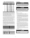
Check Oil Pressure and Compressor Stop
1. When the motor is up to full speed, note the differential
compressor oil pressure reading on the LID default screen.
It should be between 18 and 30 psid (124 to 206 kPad).
2. Press the Stop button and listen for any unusual sounds
from the compressor as it coasts to a stop.
Calibrate Motor Current Demand Setting
1. Make sure that the MOTOR RATED LOAD AMPS pa-
rameter on the SERVICE1 screen has been configured.
Place an ammeter on the line that passes through the mo-
tor load current transfer on the motor side of the power
factor correction capacitors (if provided).
2. Start the compressor and establish a steady motor current
value between 70% and 100% RLA by manually over-
riding the guide vane target value (TARGET GUIDE VANE
POS parameter on the STATUS01 screen) and setting the
chilled water set point (WATER/BRINE SETPOINT on the
STATUS01 screen) to a low value. Do not exceed 105%
of the nameplate RLA (rated load amps).
3. When a steady motor current value in the desired range
is reached, compare the MOTOR RATED LOAD AMPS
value on the STATUS01 screen to the actual amps shown
on the ammeter on the starter. Adjust the amps value on
the STATUS01 screen to match the actual value on the
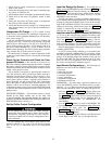
starter ammeter, if there is a difference. Highlight the amps
value; then, press the SELECT
softkey. Press the
INCREASE
or DECREASE softkey to bring the value
to that indicated on the ammeter. Press ENTER
when
the values are equal.
4. Release the target guide vane position to automatic mode.
See the section on Manual Operation of the Guide Vanes,
page 58, for instructions on how to do this.
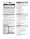
To Prevent Accidental Start-Up — The PIC can be
configured so that starting the unit is more difficult than just
pressing the LOCAL
or CCN softkeys during chiller serv-
ice or whenever necessary. Access the STATUS01
screen, and highlight the CHILLER START/STOP param-
eter. Override the value by pressing SELECT
and then the
STOP
and ENTER softkeys. The word SUPVSR ap-
pears. When attempting to restart the chiller, remember to
release the override. Access the STATUS01 screen and high-
light CHILLER START/STOP. The 3 softkeys represent 3
choices:
• START - forces the chiller ON.
• STOP - forces the chiller OFF
• RELEASE - puts the chiller under remote or schedule
control.
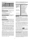
To return the chiller to normal control, press the
RELEASE
softkey; then, press the ENTER softkey. For
additional information, see Local Start-Up, page 43.
The default LID screen message indicates which com-
mand is in effect.
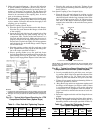
Hot Alignment Check — The operating temperatures
of various chiller components can affect the alignment of the
compressor with the heat exchangers, gear, and driver. When
all the chiller components have reached operating tempera-
ture (after running at nearly full load for 4 to 8 hours), make
a hot alignment check.
Using proper equipment and procedures, make the hot align-
ment check with either assembled or disassembled cou-
plings. The procedures are detailed in the General Mainte-
nance section, page 67.
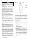
A clamping tool, Part No. TS-170, is available for check-
ing alignment without disassembling the couplings. Check
with your local Carrier representative.
Never operate the compressor or drive with the cou-
pling guards removed. Serious injury can result from
contact with rotating equipment.
Doweling — The size, quantity, and location of dowels
vary considerably with type and arrangement of gear and
drive. Check your job data for specific doweling instruc-
tions. Typical doweling practices are described in the Gen-
eral Maintenance section.
Check Chiller Operating Condition — Check to
be sure that chiller temperatures, pressures, water flows, and
oil and refrigerant levels indicate that the system is func-
tioning properly.
61