


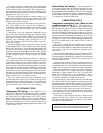
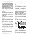
PIC System Components — The Product Integrated
Control (PIC) is the control system on the chiller. See
Table 1. The PIC controls the operation of the chiller by moni-
toring all operating conditions. The PIC can diagnose a prob-
lem and let the operator know what the problem is and what
to check. It promptly positions the guide vanes to maintain
leaving chilled water temperature. It can interface with aux-
iliary equipment such as pumps and cooling tower fans to
turn them on only when required. It continually checks all
safeties to prevent any unsafe operating condition. It also
regulates the oil heater while the compressor is off and the
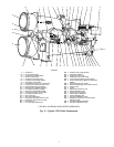
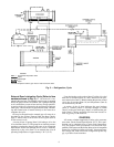
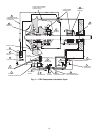
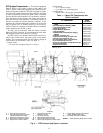
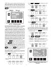
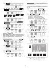
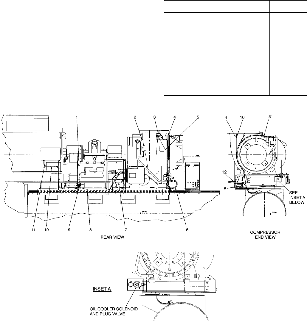
hot gas bypass valve, if installed. See Fig. 6-10 for the lo-
cations of sensors, transducers, and other devices controlled
and/or monitored by the PIC system.
The PIC can be interfaced with the Carrier Comfort
Network (CCN) if desired. It can communicate with other
PIC-equipped chillers and other CCN devices.
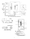
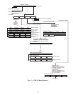
The PIC consists of 4 modules housed inside one of 3 lo-
cations: the control center, the power panel, or the starter
cabinet. The component names and the control voltage of
each location are listed below (also see Table 1):
• control center
— all extra low-voltage wiring (24 v or less)
• power panel
— 115 v control voltage
— up to 600 v for oil pump power
• starter cabinet
— chiller power wiring (per job requirement)
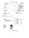
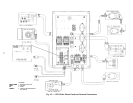
Table 1 — Major PIC Components and
Panel Locations*
PIC COMPONENT
PANEL
LOCATION
Processor Sensor Input/Output Module
(PSIO)
Control Center
Starter Management Module (SMM) Starter Cabinet
Local Interface Device (LID) Control Center
6-Pack Relay Board Control Center
8-Input Modules (Optional) Control Center
4-In/2-Out Module Power Panel
Oil Differential Pressure/Power Supply
Module
Control Center
Oil Heater Contactor (1C) Power Panel
Compressor Oil Pump Contactor (2C) Power Panel
Gear Oil Pump Contactor (5C) Power Panel
Hot Gas Bypass Relay (3C) (Optional) Power Panel
Control Transformers (T1-T4) Power Panel
Control and Oil Heater Voltage Selector (S1) Power Panel
Temperature Sensors See Fig. 7
Pressure Transducers See Fig. 7
*See Fig. 6-10.
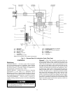
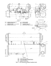
LEGEND
1—Gear Oil Pressure Sensor
2—Thrust Bearing Temperature and
Impeller Displacement Cable
3—Discharge Temperature Sensor
4—Guide Vane Conduit and Cable
5—High Pressure Cutout Switch
6—Compressor Oil Cooler
Solenoid Conduit
7—Oil Heater Conduit
8—Motor Space Heater Conduit
9—Gear Oil Temperature Sensor
10 — Motor High Temperature Switch Cable
Fig. 6 — 17EX Controls and Sensor Locations
REAR
11 — Motor Water Cooling Leak Detector
Cable (TEWAC Motor Only)
12 — Discharge Oil Pressure Sensor
TEWAC — Totally Enclosed Water-to-Air Cooled
12