


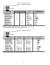
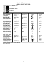
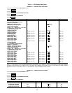
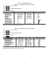
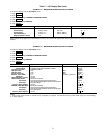

PIC System Functions
NOTE: In the rest of this manual, words not part of para-
graph headings and printed in all capital letters can be viewed
on the LID (e.g., LOCAL, CCN, RUNNING, ALARM, etc.).
Words printed both in capital letters and italics can also be
viewed on the LID and are parameters (CONTROL MODE,
COOLING SETPOINT, OVERRIDE THRESHOLD, etc.) with
associated values (e.g., modes, temperatures, pressures, per-
centages, on, off, etc.). Words printed in all capital letters
and in a box represent softkeys on the LID control panel
(e.g., ENTER
and EXIT ). See Table 2 for examples of
the information that can appear on the LID screens.
Figures 11-17 give an overview of LID operation and menus.
CAPACITY CONTROL — The PIC controls the chiller ca-
pacity by modulating the inlet guide vanes in response to
chilled water temperature changes away from the WATER/
BRINE CONTROL POINT. The WATER/BRINE CONTROL
POINT may be changed by a CCN network device or is de-
termined when the PIC adds any active chilled water reset to
the chilled water SET POINT. The PIC uses the PROPOR-
TIONAL INC (Increase) BAND, PROPORTIONAL DEC
(Decrease) BAND, and the PROPORTIONAL ECW (Enter-
ing Chilled Water) GAIN to determine how quickly or slowly
to respond. WATER/BRINE CONTROLPOINT may be viewed/
overridden from the STATUS menu, STATUS01 screen.
ENTERING CHILLED WATER CONTROL — If this op-
tion is enabled, the PIC uses the ENTERING CHILLED WA-
TER temperature to modulate the vanes instead of the LEAVING
CHILLED WATER temperature. The ENTERING CHILLED
WATER control option may be viewed/modified from the
CONFIG screen, accessed from the EQUIPMENT CON-
FIGURATION table.
DEADBAND — This is the tolerance on the chilled water/
brine temperature WATER/BRINE CONTROL POINT. If the
water temperature goes outside the WATER/BRINE DEAD-
BAND, the PIC opens or closes the guide vanes in response
until it is within tolerance. The PIC may be configured with
a 0.5° to 2° F (0.3° to 1.1° C) deadband. WATER/BRINE
DEADBAND may be viewed or modified from the
SERVICE1 screen, accessed from the EQUIPMENT
SERVICE table.
For example, a 1° F (0.6° C) deadband setting controls
the water temperature within ±0.5° F (0.3° C) of the control
point. This may cause frequent guide vane movement if the
chilled water load fluctuates frequently. A value of
1° F (0.6° C) is the default setting.
PROPORTIONAL BANDSAND GAIN — Proportional band
is the rate at which the guide vane position is corrected in
proportion to how far the chilled water/brine temperature is
from the control point. Proportional gain determines how
quickly the guide vanes react to how quickly the tempera-
ture is moving from WATER/BRINE CONTROL POINT. Pro-
portional bands and gain values can be viewed/modified from
the SERVICE3 screen (accessed from the EQUIPMENT CON-
FIGURATION table) and the MAINT01 screen (accessed from
the CONTROL ALGORITHM STATUS table).
The Proportional Band — There are two response modes,
one for temperature response above the control point, the
other for response below the control point.
The first type is called PROPORTIONAL INC BAND, and
it can slow or quicken vane response to chilled water/brine
temperature above the WATER/BRINE DEADBAND.Itcan
be adjusted from a setting of 2 to 10; the default setting is
6.5. PROPORTIONAL DEC BAND can slow or quicken vane
response to chilled water temperature below deadband plus
the control point. It can be adjusted on the LID from a set-
ting of 2 to 10, and the default setting is 6.0. Increasing ei-
ther of these settings causes the vanes to respond more slowly
than at a lower setting.
The PROPORTIONAL ECW GAIN can be adjusted at the LID
display from a setting of 1.0 to 3.0, with a default setting of
2.0. Increase this setting to increase guide vane response to
a change in entering chilled water temperature.
DEMAND LIMITING — The PIC responds to the ACTIVE
DEMAND LIMIT set point by limiting the opening of the
guide vanes. It compares the set point to either COMPRES-
SOR MOTOR LOAD or COMPRESSOR MOTOR LOAD CUR-
RENT (percentage), depending on how the control is con-
figured for the DEMAND LIMIT SOURCE which is accessed
on the SERVICE1 screen. The default setting is current
limiting. The ACTIVE DEMAND LIMIT may be viewed on
the STATUS01 screen.
CHILLER TIMERS — The PIC maintains 2 runtime clocks,
known as COMPRESSOR ONTIME and SERVICE
ONTIME. COMPRESSOR ONTIME indicates the total life-
time compressor run hours. This timer can register up to
500,000 hours before the clock turns back to zero. The SERV-
ICE ONTIME is a resettable timer that can be used to indi-
cate the hours since the last service visit or any other event.
The time can be changed from the LID to whatever value is
desired. This timer can register up to 32,767 hours before it
rolls over to zero.
The chiller also maintains a start-to-start timer and a stop-
to-start timer. These timers limit how soon the chiller can be
started. See the Start-Up/Shutdown/Recycle Sequence sec-
tion, page 43, for operational information.
OCCUPANCY SCHEDULE — The chiller schedule, de-
scribed in the Time Schedule Operation section, page 18,
determines when the chiller can run. Each schedule consists
of 1 to 8 occupied/unoccupied time periods, set by the op-
erator. These time periods can be enabled (or not enabled)
on each day of the week and for holidays. The day begins
with 0000 hours and ends with 2400 hours. The chiller is in
an occupied state unless an unoccupied time period is in
effect.
NOTE: To determine whether or not the chiller is in an oc-
cupied state and can be started, access the STATUS01 screen
and scroll to the OCCUPIED? parameter. If the value in the
right column is YES, the chiller is in an occupied state and
can turn on or can be started. If the value is NO, the chiller
is in an unoccupied state; that is, it can shut down or cannot
be started without performing an override.
The schedules can be set to follow the building schedule
or to be in an occupied state 100% of the time. The sched-
ules also can be bypassed by forcing the CHILLER START/
STOP parameter on the STATUS01 screen to START. For
more information on forced starts, see Local Start-Up,
page 43. The schedules also can be overridden to keep the
chiller in an occupied state for up to 4 hours, on a one-time
basis.
NOTE: A parameter value can be ЉforcedЉ (changed by an
operator) from the LID screen or from another control de-
vice such as a CCN terminal. For example, if the CHILLER
START/STOP parameter is set to START, the operator can
go to the LID and change the value to STOP to ЉforceЉ the
chiller to stop.
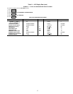
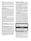
Figure 14 shows a schedule for a typical office building
time schedule, with a 3-hour, off-peak cool down period from
midnight to 3 a.m., following a weekend shutdown. For ex-
ample, holiday periods are set to be unoccupied 24 hours per
day. The building operates Monday through Friday, 7:00 a.m.
to 6:00 p.m., with a Saturday schedule of 6:00 a.m. to
1:00 p.m., and includes the Monday midnight to 3:00 a.m.
weekend cool-down schedule.
32