


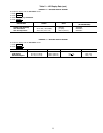
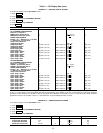
NOTE: This schedule is for illustration only, and is not in-
tended to be a recommended schedule for chiller operation.
Depending on its operating mode, the chiller uses the fol-
lowing occupancy schedules:
• LOCAL mode — Occupancy Schedule 01(OCCPC01 on
the SCHEDULE screen).
• ICE BUILD mode — Occupancy Schedule 02 (OC-
CPC02 on the SCHEDULE screen).
• CCN mode — Occupancy Schedule 03-99 (OCCPC02-
OCCPC99 on the SCHEDULE screen).
The CCN schedule number is specified on the CONFIG
screen, which is accessed from the EQUIPMENT CON-
FIGURATION table. The schedule number can be any value
from 03 to 99. If this schedule number is changed on the
CONFIG screen, the operator must use theATTACHTO NET-
WORK DEVICE screen to upload the new number into the
schedule screen. See Fig. 12.
Safety Controls — The PIC monitors all safety control
inputs, and if required, shuts down the chiller or limits the
guide vanes to protect the chiller from possible damage from
several conditions, including:
• high bearing temperature
• high motor winding temperature
• high discharge temperature
• low compressor oil pressure
• low gear oil pressure
• high gear oil temperature
• low cooler refrigerant temperature/pressure
• condenser high pressure or low pressure
• inadequate water/brine cooler and condenser flow
• high, low, or loss of voltage
• excessive motor acceleration time
• excessive starter transition time
• lack of motor current signal
• excessive motor amps
• excessive compressor surge
• temperature and transducer faults
Starter faults or optional protective devices within the starter
can shut down the chiller. These devices depend on what
options have been purchased.
If a compressor motor overload or ground fault occurs,
check the motor for grounded or open phases before at-
tempting a restart.
If the PIC control initiates a safety shutdown, the control
displays a primary and secondary alarm message on the LID,
energizes an alarm relay in the starter, and blinks the alarm
light on the control panel. The alarm information is stored in
memory and can be viewed on the LID by accessing the
ALARM HISTORY table along with a troubleshooting
message.
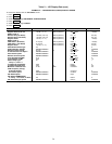
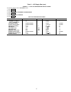
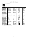
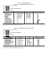
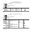
To give a more specific operating condition warning, the
operator can also define alert limits on various monitored
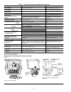
inputs. Safety contact and alert limits are defined in Table 3.
Alarm and alert messages are listed in the Troubleshooting
Guide section, page 83.
SHUNT TRIP — The PIC can include an optional shunt trip
function that acts as a safety trip. The shunt trip is wired
from an output on the SMM to the motor circuit breaker. If
the PIC tries to shut down the compressor using normal shut-
down procedures but is unsuccessful for 30 seconds, the shunt
trip output is energized and trips off the circuit breaker. If
ground fault protection has been applied to the starter, the
ground fault trip also energizes the shunt trip to trip the cir-
cuit breaker.
Default Screen Freeze — When the chiller is in an
alarm state, the default LID display freezes; that is, it stops
updating. The first line of the LID default screen displays a
primary alarm message; the second line displays a second-
ary alarm message. The LID default screen freezes to allow
the operator to see the condition of the chiller at the time of
the alarm. Knowledge of the operating state of the chiller at
the time an alarm occurs is useful when troubleshooting. Cur-
rent chiller information can be viewed on the STATUS screens
(see Table 2, Examples 1-4). Once all existing alarms are
cleared by pressing the RESET
softkey, the default LID
screen returns to normal operation.
Auxiliary Compressor Oil Pump Control — The
compressor oil pump (optional) is controlled by the PIC. If,
during start-up, the main oil pump cannot raise pressure to
18 psi (124 kPa), the auxiliary oil pump (optional) is ener-
gized. During compressor operation, the auxiliary oil pump
is energized if the oil pressure falls below the alert threshold
(18 psi [124 kPa]). Once the auxiliary compressor oil pump
is running, it stays on until the compressor is turned off and
is deenergized along with the main oil pump after the post-
lubrication period.
Auxiliary Gear Oil Pump Control — The optional
auxiliary gear oil pump is controlled by the PIC. During start-
up, if the main gear oil pump cannot raise the oil pressure at
least 20 psi (139 kPa), the auxiliary gear oil pump is ener-
gized. If, after 30 seconds, the required oil pressure has not
been established, the PIC initiates an alarm and does not al-
low the chiller to start. During operation, the auxiliary gear
oil pump is energized if the oil pressure falls below the alert
threshold (15 to 20 psi [103 to 139 kPa]). Once the auxiliary
gear oil pump is running, it stays on until the compressor is
turned off and is deenergized with the main gear oil pump
after the post-lubrication period.
Shaft Seal Oil Control — For all open-drive chillers,
the shaft seal must be bathed in oil at all times, especially
when the chiller is not running. This ensures that refrigerant
will not leak past the seal. The PIC energizes the compressor
oil pump for one minute if the oil pump has not operated
during the past 12 hours.
IMPORTANT: If control power is turned off for more
than 12 hours, the refrigerant charge must be pumped
into the economizer/storage vessel. Because the oil heater
is also turned off during this time, storing the refrig-
erant prevents refrigerant from migrating into the oil.
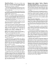
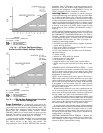
Ramp Loading Control — Ramp loading control slows
down the rate at which the compressor loads up. It prevents
the compressor from loading up during the short time be-
tween chiller start-up and the time the chilled water loop has
to be brought down to normal design conditions. Ramp load-
ing helps to reduce electrical demand by slowly bringing the
chilled water temperature to the control point temperature.
The total power draw during this period stays almost
unchanged.
The PIC bases ramp loading on either the chilled water
temperature or on motor load. See the Table 2, Example 6
(CONFIG screen).
1. The temperature ramp loading rate is an operator-
configured value that limits the rate at which either the
leaving chilled water or entering chilled water tempera-
ture decreases (TEMP PULLDOWN DEG/MIN param-
eter on the CONFIG screen). The lowest temperature ramp
rate is used the first time the chiller is started (at com-
missioning). The lowest temperature ramp rate is also used
if chiller power has been off for 3 hours or more (even if
the motor ramp load control method has been selected).
33