


1. Check that all wiring connections are properly termi-
nated to the starter.
2. Verify that the ground wire to the starter is installed prop-
erly and is of sufficient size.
3. Verify that the motors are properly grounded to the starter.
4. Check that all the relays are properly seated in their
sockets.
5. Verify that the proper AC input voltage is brought into
the starter per the certified drawings.
6. Verify that the initial factory settings (i.e., starting torque,
ramp potentiometers, etc.) are set per the manufacturer’s
instructions.
Compressor Oil Charge — If oil is added, it must
meet Carrier’s specification for centrifugal compressor use
as described in the Scheduled Maintenance, Oil Specifica-
tions section (page 77).
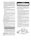
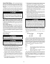
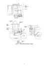
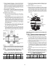
Oil may be added through the compressor oil drain and
charging valve (Fig. 2, Item 22) using a pump. The pump
must be able to lift from 0 to 150 psig (0 to 1034 kPa), or
above chiller pressure. However, an oil charging elbow on
the seal-oil return chamber (Fig. 4, Item 3) allows oil to be
added without pumping. The seal oil return pump automati-
cally transfers the oil to the main oil reservoir.
Oil should only be charged or removed when the chiller
is shut down. Maximum oil level is the middle of the upper
sight glass.
Power Up the Controls and Check the Com-
pressor Oil Heater —
Be sure that an oil level is vis-
ible in the compressor before energizing the controls.Aseparate
disconnect energizes the oil heater and the control circuit.
When first powered, the LID should display the default screen
within a short period of time.
The oil heater is energized by powering the control cir-
cuit. This should be done several hours before start-up to
minimize oil-refrigerant dilution. The oil heater is con-
trolled by the PIC and is powered through a contactor in the
power panel. Starters contain a separate circuit breaker to
power the heater and the control circuit. This arrangement
allows the heater to energize when the main motor circuit
breaker is off for service work or extended shutdowns. The
oil heater relay status can be viewed on the STATUS02 screen
on the LID. Oil sump temperature can be viewed on the LID
default screen.
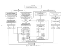
SOFTWARE VERSION — The software version is always
labeled on the PSIO module and on the back side
of the LID module. The software number also appears on
both the CONTROLLER IDENTIFICATION and LID CON-
FIGURATION tables. See Fig. 15.
Set Up Chiller Control Configuration
Do not operate the chiller before the control configu-
rations have been checked and a Control Test has been
satisfactorily completed. Protection by safety controls
cannot be assumed until all control configurations have
been confirmed.
As you configure the 17EX chiller, write down all con-
figuration settings. A log, such as the one shown on pages
CL-1 to CL-12, is a convenient way to list configuration
values.
Input the Design Set Points — To modify the set
points, access the SETPOINT menu. (Press the MENU
and
SETPOINT
softkeys.) From this menu, you can modify the
base demand limit and the leaving chilled water, entering
chilled water, and ice build set points. See Fig. 15 for the
SETPOINT menu structure.
The PIC can control a set point according to ether the leav-
ing or entering chilled water temperature. To change the type
of control, access the CONFIG screen. Scroll down to high-
light ECW CONTROL OPTION. To control the set point ac-
cording to the leaving chilled water, press the DISABLE
softkey; to control the set point according to the entering
chilled water, press the ENABLE
softkey.
Input the Local Occupied Schedule (OCCPC01S)
—
To set up the occupied time schedule according to the
site requirements, access the SCHEDULE screen on the LID.
(Press the MENU
and SCHEDULE softkeys.) The de-
fault, factory-set schedule is 24 hours, occupied 7 days per
week including holidays. For more information about how
to set up a time schedule, see the Controls section, page 11.
If the ice build option is being used, configure the ice build
schedule (OCCPC02S).
If a CCN system is being installed or if a secondary time
schedule is required, configure the CCN occupancy sched-
ule (OCCPC03S to OCCPC99S). This task is normally done
using a CCN Building Supervisor terminal, but it can also
be done at the LID. For more information on CCN func-
tions, see 17EX CCN supplement. Also, in this manual, see
the section on Occupancy Schedule, page 32.
Input Service Configurations — The following con-
figurations are done from the SERVICE menu:
• password
• input time and date
• LID configuration
• controller identification
• service parameters
• equipment configuration
• automated control test
PASSWORD — You must enter a password whenever you
access the SERVICE screens. The default, factory-set pass-
word is1-1-1-1.Thepassword may be changed from the
LID CONFIGURATION screen. To change the password:
1. Press the MENU
and SERVICE softkeys. Enter your
password and highlight LID CONFIGURATION. Press
the SELECT
softkey. Only the last 5 entries on the LID
CONFIGURATION screen can be changed: BUS #,
ADDRESS #, BAUD RATE, US IMP/METRIC, and
PASSWORD.
2. Use the ENTER
softkey to scroll to PASSWORD. The
first digit of the password is highlighted on the LID screen.
3. To change the digit, press the INCREASE
or
DECREASE
softkey. When you see the digit you want,
press the ENTER
softkey.
4. The next digit is highlighted. Change it and the third and
fourth digits in the same way you changed the first.
54