


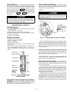
The rotation direction of the motor is shown either on the
motor nameplate or on the certified drawing. Information on
the required phase rotation of the incoming power for this
motor may also be found on the nameplate or drawing. If
either is unknown, the correct sequence can be determined
as follows. While the motor is uncoupled from the load, start
the motor and observe the direction of rotation. Allow the
motor to achieve full speed before disconnecting it from the
power source. Refer to Motor Pre-Start Checks (page 51)
for information concerning initial start-up. If the resulting
rotation is incorrect, it can be reversed by interchanging any
2 incoming cables.
Motor Auxiliary Devices — Auxiliary devices such
as resistance temperature detectors, thermocouples, thermo-
guards, etc., generally terminate on terminal blocks located
in the auxiliary terminal box on the motor. Other devices
may terminate on their own enclosures elsewhere on the mo-
tor. Such information can be obtained by referring to the cer-
tified drawing. Information regarding terminal designations
and the connection of auxiliary devices can be obtained from
the auxiliary drawings referenced by the outline drawing.
If the motor is provided with internal space heaters, to
ensure proper heater operation, the incoming voltage sup-
plied to them must be exactly as shown by either the name-
plate on the motor or the outline drawing. Exercise caution
any time contact is made with the incoming space heater cir-
cuit, because space heater voltage is often automatically ap-
plied when the motor is shut down.
Open Oil Circuit Valves — Check that the oil filter
isolation valves for both the compressor and external gear
are open by removing the valve cap and checking the valve
stem. (See Scheduled Maintenance, Changing the Oil Fil-
ters, page 76.)
Tighten All Gasketed Joints and Guide Vane
Shaft Packing —
Gaskets and packings normally relax
by the time the chiller arrives at the jobsite. Tighten all gas-
keted joints and the guide vane shaft packing to ensure a
leak-tight chiller.
NOTE: Check the chiller cold alignment. Refer to Chiller
Alignment in the General Maintenance section, page 71.
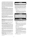
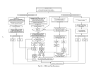
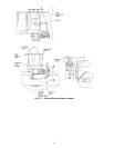
Check Chiller Tightness — Figure 25 outlines the
proper sequence and procedures for leak testing.
17EX chillers may be shipped with the refrigerant con-
tained in the economizer/storage vessel and the oil charge
shipped in the compressor. The cooler/condenser vessels have
a 15 psig (103 kPa) refrigerant charge. Units may also be
ordered with the refrigerant shipped separately, along with a
15 psig (103 kPa) nitrogen-holding charge in each vessel.
To determine if there are any leaks, the chiller should be
charged with refrigerant. Use an electronic leak detector to
check all flanges and solder joints after the chiller is pres-
surized. If any leaks are detected, follow the leak test
procedure.
If the chiller is spring isolated, keep all springs blocked in
both directions in order to prevent possible piping stress and
damage during the transfer of refrigerant from vessel to ves-
sel during the leak test process or any time refrigerant is trans-
ferred. Adjust the springs when the refrigerant is in operat-
ing condition and when the water circuits are full.
Refrigerant Tracer — Carrier recommends using an en-
vironmentally acceptable refrigerant tracer for leak testing
with an electronic detector.
Ultrasonic leak detectors also can be used if the chiller is
under pressure.
Do not use air or oxygen as a means of pressurizing the
chiller. Some mixtures of HFC-134a and air can un-
dergo combustion.
Leak Test the Chiller — Due to regulations regarding
refrigerant emissions and the difficulties associated with sepa-
rating contaminants from refrigerant, Carrier recommends
the following leak test procedures. See Fig. 25 for an outline
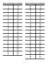
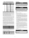
of the leak test procedures. Refer to Tables 5A and 5B for
refrigerant pressure/temperature values and to the Pumpout
and Refrigerant Transfer Procedures section, page 63.
1. If the pressure readings are normal for the chiller
condition:
a. Evacuate the nitrogen holding charge from the ves-
sels, if present.
b. Raise the chiller pressure, if necessary, by adding re-
frigerant until the pressure is at an equivalent satu-
rated pressure for the surrounding temperature. Follow
the pumpout procedures in the Pumpout and Refrig-
erant Transfer Procedures section, page 63.
Never charge liquid refrigerant into the chiller if the pres-
sure in the chiller is less than 35 psig (241 kPa). Charge
as a gas only, with the cooler and condenser pumps run-
ning, until this pressure is reached, using PUMPDOWN/
LOCKOUT and TERMINATE LOCKOUT mode on the
PIC. Flashing of liquid refrigerant at low pressures can
cause tube freeze-up and considerable damage.
Run the chiller water pumps whenever transferring, re-
moving, or charging refrigerant.
c. Leak test chiller as outlined in Steps3-9.
2. If the pressure readings are abnormal for chiller
conditions:
a. Prepare to leak test chillers shipped with refrigerant
(Step 2h).
b. Check for large leaks by connecting a nitrogen bottle
and raising the pressure to 30 psig (207 kPa). Soap
test all joints. If the test pressure holds for 30 minutes,
prepare to test for small leaks (Steps 2g - h).
c. Plainly mark any leaks that are found.
d. Release the pressure in the system.
e. Repair all leaks.
f. Retest the joints that were repaired.
g. After successfully completing the test for large leaks,
remove as much nitrogen, air, and moisture as pos-
sible, given the fact that small leaks may be present in
the system. This can be accomplished by following
the dehydration procedure, outlined in the Chiller
Dehydration section, page 49.
h. Slowly raise the system pressure to the equivalent satu-
rated pressure for the surrounding temperature but no
less than 35 psig (241 kPa) by adding HFC-134a
refrigerant. Proceed with the test for small leaks
(Steps 3-9).
3. Check the chiller carefully with an electronic leak detec-
tor, or soap bubble solution.
46