


2. Direct current (as from a welder) can be passed through
the winding. The total current should not exceed approxi-
mately 50% of the rated full load current. If the motor
has only 3 leads, 2 must be connected together to form
one circuit through the winding. In this case, one phase
carries the full applied current and each of the others car-
ries half of the applied current. If the motor has 6 leads
(3 mains and 3 neutrals), the 3 phases should be con-
nected into one series circuit.
3. Heated air can be blown either directly into the motor or
into a temporary enclosure surrounding the motor. The
source of heated air should preferably be electrical vs.
fueled (such as kerosene), since a malfunction of the fuel
burner could result in carbon entering the motor. Exer-
cise caution when heating the motor with any source of
heat other than self-contained space heaters. Raise the wind-
ing temperature at a gradual rate to allow any entrapped
moisture to vaporize and escape without rupturing the in-
sulation. The entire heating cycle should extend over 15
to 20 hours.
Insulation resistance measurements can be made while the
winding is being heated. However, they must be corrected to
104 F (40 C) for evaluation since the actual insulation re-
sistance decreases with increasing temperature. For a new
winding, the insulation resistance approximately halves for
each 18° F (10° C) increase in insulation temperature above
the dew point.
Motor Pre-Start Checks — To prevent damage to the
motor, the following steps must be taken before initial start-
up:
1. Remove the shaft shipping brace (if supplied).
2. For sleeve bearing motors, the oil reservoir must be filled
with oil to the correct level. Use a rust and oxidation in-
hibited, turbine grade oil. The viscosity of the oil must be
32 ISO (150 SSU) at 100 F (37.7 C). Oil capacity in each
of the two bearings is 0.6 gal. (2.3 L) per bearing. Use of
Carrier Oil Specification PP16-0 is approved, Carrier Part
No. PP23BZ091 (Mobil DTE Light or Texaco Regal
R+O32).
3. If possible, the shaft should be turned over by hand to
ensure that there is free rotation. On sleeve bearing mo-
tors, the shaft should be moved to both extremes of its
end play while it is being rotated, and the oil rings should
be viewed through the viewing ports in the top of the bear-
ing housing to verify free ring rotation.
4. On fan-cooled motors, the area around the external fan
inlet should be checked for loose debris that could be drawn
into the fan during operation.
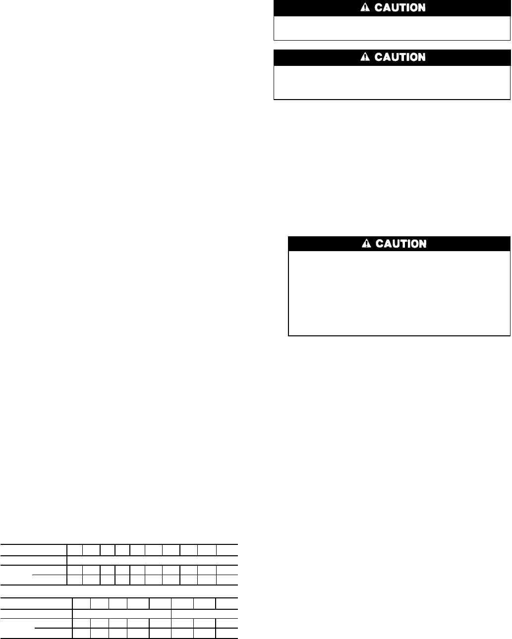
5. All external, factory-made, bolted joints should be checked
for any looseness that may have occurred in transit. Refer
to Table 6 for recommended bolt torques.
Table 6 — Recommended Motor Fastener
Tightening Torques
Bolt size
1
⁄
4
؆
5
⁄
16
؆
3
⁄
8
؆
1
⁄
2
؆
5
⁄
8
؆
3
⁄
4
؆
7
⁄
8
؆ 1؆ 1
1
⁄
3
؆ 1
1
⁄
2
؆
Grade SAE GR 5
Torque*
Ft-lbs 3.5 7 12 31 63 115 180 275 550 960
N
.
m 4.7 9.5 16 42 85 156 244 373 746 1302
Bolt size M4 M6 M8 M10 M12 M10 M12 M16
Grade DIN 8.8 DIN 12.9
Torque*
Ft-lbs 2 8 15 35 65 45 92 225
N
.
m 2.7 11 20 47 88 61 125 305
*Torque values based upon dry friction.
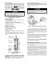
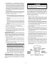
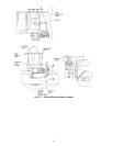
External Gear Pre-Start Checks
There are 2 service valves on the external gear oil lines.
See Fig. 27. Open both valves before starting the chiller.
External gears are shipped without oil. Before start-up,
the gear must be filled with the proper type and amount
of oil.
Before starting the external gear, check for any signs of
mechanical damage, such as damaged piping or accessories.
Then, follow the procedures listed below.
1. Fill the gear and auxiliary sump (if applicable) with oil
to the level indicated next to the sight glass. Fill the gear
to the proper level as follows. Make sure all external pip-
ing, gear oil cooler, and pumps are filled before confirm-
ing the final oil level. Fill to the oil level indicated next
to the glass sight gage.
Add oil through the gear inspection cover. The inspection
cover must be removed in order to add oil. Take care to
seal the cover when it is replaced.
Never attempt to add or replace oil while the ex-
ternal gear is running unless a vertical sight glass is
in use and the running oil level has been established
and marked on the sight glass. Do not fill beyond
the indicated oil level. Excess lubrication increases
the churning effect and may result in overheating and
subsequent thinning of oil and possible damage to
the rotating components.
2. The viscosity of the oil must be 68 ISO. Use of Carrier
oil, specification PP16-2 is approved (Mobil DTE Heavy
Medium or Texaco Regal UR & 068; Carrier Part No.
PP23BB005).
3. Check that all electrical connections have been made and
are in working order. Check that all accessories are prop-
erly mounted.
4. Turn the gear shafts by hand with a spanner wrench to
confirm that there are no obstructions to rotation.
5. Check that all couplings are properly aligned, mounted,
and keyed on the shaft extension.
6. Check that the inspection cover is securely fastened. See
Table 7 for recommended torque values.
7. For units operating in cold ambient temperatures, op-
tional heaters must be turned on and the oil temperature
must be allowed to rise to at least 60 F (16 C) before
start-up.
8. Start the chiller under as light a load as possible. Check
for oil leaks, unusual sounds, excessive vibration, and ex-
cessive heat. If an operating problem develops, shut down
immediately and correct the problem before restarting.
51