


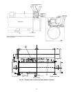
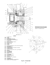
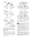
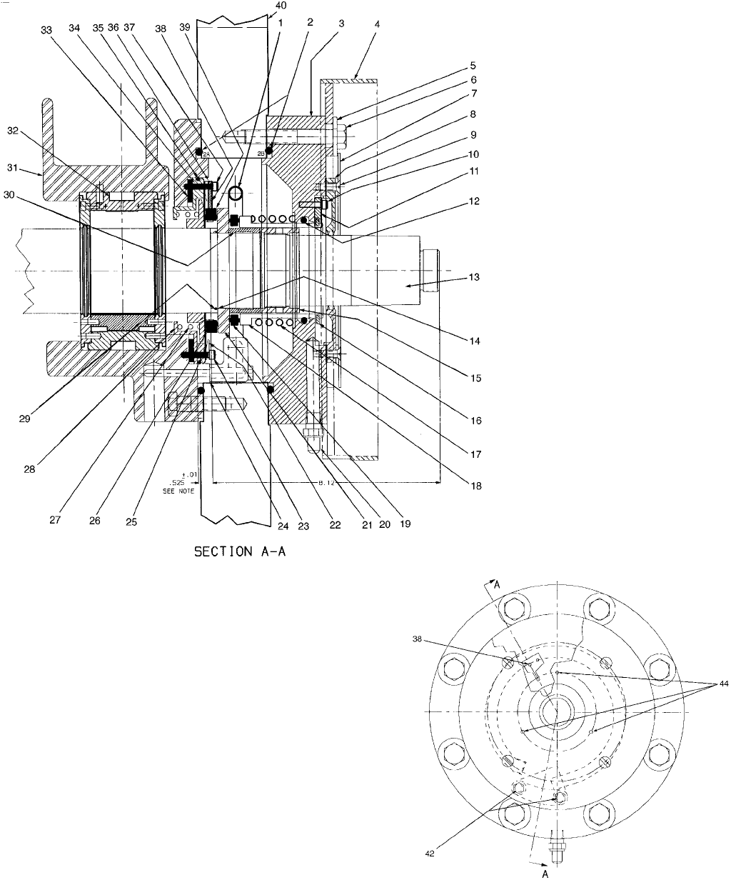
LEGEND
1—Lubricating Tube
2A — O-Ring
2B — O-Ring
3—Seal Housing
4—Coupling Guard Mounting Ring
5—Plain
1
⁄
2
-in. Washer (8 Required)
6—Hex Head Bolt,
1
⁄
2
-13×4lg(8Required)
7—Windage Baffle
8—Shaft End Labyrinth
9—Screw
1
⁄
4
-20×
3
⁄
4
lg (4 Required)
10 — Screw, 10-24 ×
1
⁄
2
lg
11 — Key, Contact Sleeve
12 — O-Ring
13 — Compressor Shaft
14 — O-Ring
15 — Lock Nut
16 — Snap Ring (Service tool only; must be removed for operation)
17 — Spring Contact Sleeve
18 — Contact Sleeve
19 — Outer Carbon Ring
20 — Coupling (Connection to atmospheric oil chamber)
21 — Rotating Contact Ring
22 — Diaphragm Retainer
23 — Inner Seal Retaining Screw, 10-24×1lg(14Required)
24 — Gasket
25 — Diaphragm
26 — Inner Carbon Ring
27 — Inner Seal Spring
28 — Inner Seal Retainer
29 — Seal Gland Sleeve
30 — Spacer
31 — Journal Bearing Housing
32 — Journal Bearing
33 — Inner Seal Shim
34 — Inner Carbon Guide Ring
35 — O-Ring
36 — Inner Carbon Key
37 — Screw, 10-24 × 1
1
⁄
4
lg (2 Required)
38 — Retaining Ring
39 — Seal Shoulder
40 — Compressor End Wall
41 — Thread Cut Screw, 8-32 ×
1
⁄
4
lg (3 Required)
42 — Screw,
5
⁄
16
-18×1
3
⁄
4
lg (2 Required)
Fig. 36 — Contact Seal
NOTE: Adjust shims (Item 33) to main-
tain .525 ± .01 in. (13.3 ± .3 mm) dimen-
sionwithshaft thrusttowarddriveand check
carbon for +.06 minimum travel.
69