


2. To determine economizer/storage vessel pressure, attach
a 30 in.-0-400 psi (-101-0-2760 kPa) gage to the vessel.
3. Refer to Fig. 32 for valve locations and numbers.
Transfer, addition, or removal of refrigerant in spring-
isolated chillers may place severe stress on external pip-
ing if springs have not been blocked in both up and down
directions.
Transferring Refrigerant into the Economizer/
Storage Vessel —
These steps describe the method of
moving refrigerant from the cooler/condenser/compressor sec-
tions into the economizer/storage vessel. This is normally
done to prepare for service work on the cooler, condenser, or
the compressor components or for long-term chiller
shutdown.
1. Isolate and push refrigerant into the economizer/storage
vessel with the pumpout compressor.
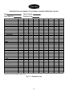
a. Valve positions: (Blank spaces indicate open valves).
VALVE 1 2 3 4 5 6 7 8 9 10 11
CONDITION CC CCC C
b. Turn off the chiller water pumps and pumpout con-
denser water.
c. Turn on pumpout compressor to push liquid out of the
cooler/condenser/compressor section.
d. When all liquid has been pushed into the economizer/
storage vessel, close the cooler isolation valve 7.
e. Access the CONTROL TEST table on the LID. Select
the PUMPDOWN/LOCKOUT screen. From this screen,
turn on the chiller water pumps and view the chiller
pressures.
f. Turn off pumpout compressor.
2. Evacuate refrigerant gas from the cooler/condenser/
compressor vessel.
a. Valve positions: close valves 2 and 5, open valves 3
and 4.
VALVE 1 2 3 4 5 6 7 8 9 10 11
CONDITION C C CCCC C
b. Turn on the pumpout condenser water.
c. Run the pumpout compressor until the suction reaches
15 in. Hg (50 kPa abs). Monitor pressures on the LID
and on the refrigerant gages.
d. Close valve 1.
e. Turn off pumpout compressor.
f. Close valves 3, 4, and 6. (All valves are now closed.)
g. Turn off pumpout condenser water.
h. Use the PUMPDOWN LOCKOUT screen on the LID
to turn off the chiller water pumps and to lock out the
chiller compressor from operation.
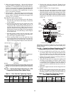
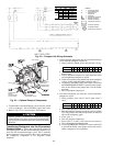
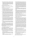
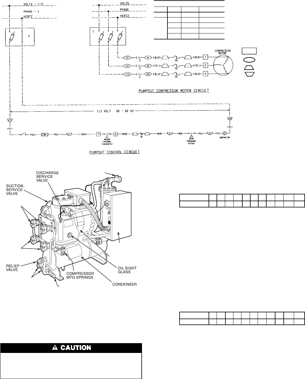
Fig. 33 — Pumpout Unit Wiring Schematic
LEGEND
1—Compressor Motor
Circuit Disconnect
2—Control Circuit
Disconnect
C—Contactor
OL — Compressor Overload
RLA — Rated Load Amps
T’stat — Internal Thermostat
Compressor Terminal
Contactor Terminal
Overload Terminal
Pumpout Unit Terminal
COMPRESSOR MOTOR
Hz Ph Volts Max. RLA
50 3 400 4.7
60
3 298 10.9
3 230 9.5
3 460 4.7
3 375 3.8
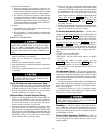
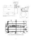
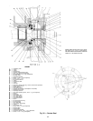
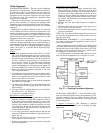
CONDENSER
WATER
CONNECTIONS
(FIELD PIPING)
CONDENSER
DISCHARGE VALVE
VENT VALVE
CONTROL BOX
(WIRING BY
CONTRACTOR)
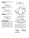
COMPRESSOR
VALVES
VALVES
Fig. 34 — Optional Pumpout Compressor
66