


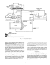

The chiller compressor continuously draws large quanti-
ties of refrigerant vapor from the cooler at a rate determined
by the amount of guide vane opening. This compressor suc-
tion reduces the pressure within the cooler, allowing the liq-
uid refrigerant to boil vigorously at a fairly low temperature
(typically 38 to 42 F [3 to 6 C]).
The liquid refrigerant obtains the energy needed to va-
porize by removing heat from the water or brine in the cooler
tubes. The cold water or brine can then be used in air con-
ditioning and/or other processes.
After removing heat from the water or brine, the refrig-
erant vapor enters the first stage of the compressor, is
compressed, and flows into the compressor second stage. Here
it is mixed with flash-economizer gas and is further
compressed.
Compression raises the refrigerant temperature above
that of the water flowing through the condenser tubes.
When the warm (typically 98 to 102 F [37 to 40 C]) refrig-
erant vapor comes into contact with the condenser tubes, the
relatively cool condensing water (typically 85 to 95 F
[29 to 35 C]) removes some of the heat, and the vapor con-
denses into a liquid.
The liquid refrigerant passes through an orifice into the
FLASC chamber. The coolest condenser water flows through
the FLASC and allows a lower saturated temperature and
pressure. Part of the entering liquid refrigerant will flash to
vapor once it has passed through the FLASC orifice, thereby
cooling the remaining liquid. The vapor is then recondensed
by the condenser water flowing through the FLASC
chamber.
The subcooled liquid refrigerant drains into a high-side
valve chamber that meters the refrigerant liquid into a flash
economizer chamber. Pressure in this chamber is interme-
diate between condenser and cooler pressures. At this lower
pressure, some of the liquid refrigerant flashes to gas, fur-
ther cooling the remaining liquid. The flash gas, having ab-
sorbed heat, is returned directly to the compressor second
stage. Here it is mixed with discharge gas that is already com-
pressed by the first-stage impeller. Since the flash gas has to
pass through only half the compression cycle to reach con-
denser pressure, there is a savings in power.
The cooled liquid refrigerant in the economizer is me-
tered through the low-side valve chamber, reducing the re-
frigerant pressure. Pressure in the cooler is lower than in the
economizer. Some of the liquid flashes as it passes through
the low side float valve. The cycle is now complete.
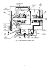
OIL COOLING CYCLE
Compressor Oil Cooling —
The compressor oil is
water cooled. Water flow through the oil cooler is manually
adjusted by a plug valve to maintain an operating tempera-
ture at the reservoir of approximately 145 F (63 C). An oil
heater in the reservoir helps to prevent oil from being di-
luted by the refrigerant. The heater is controlled by the PIC
(Product Integrated Control) and is energized when the oil
temperature is outside the operating temperature range of 150
to 160 F (66 to 71 C).
External Gear Oil Cooling — The external gear oil
is also water cooled. Water flow through the gear oil cooler
is manually adjusted by a plug valve to maintain an oper-
ating temperature of approximately 130 F (54 C). If so equipped,
an oil heater in the reservoir helps to maintain the oil tem-
perature under cold ambient operating conditions. The heater
is controlled by an internal thermostat.
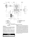
LUBRICATION CYCLE
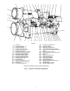
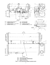
Compressor Lubrication Cycle (Refer to item
numbers shown in Fig. 4) —
The compressor oil
pump and oil reservoir are contained in the compressor base.
Oil is pumped through an oil cooler and filter to remove heat
and any foreign particles. A portion of the oil is then di-
rected to the shaft-end bearing and the shaft seal. The bal-
ance of the oil lubricates the thrust and journal bearings and
the thrust end seal. The bearing and transmission oil returns
directly to the reservoir to complete the cycle. Contact-seal
oil leakage, however, is collected in an atmospheric float cham-
ber to be pumped back to the main reservoir as the oil
accumulates.
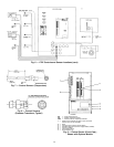
Oil may be charged into the compressor oil reservoir
(Item 8) through a charging valve (Item 6) which also func-
tions as an oil drain. If there is refrigerant in the chiller, how-
ever, a hand pump will be required for charging at this
connection.
An oil-charging elbow (Item 3) on the seal-oil return cham-
ber allows oil to be added without pumping. The seal-oil re-
turn pump (Item 4) automatically transfers the oil to the main
reservoir. Sight glasses (11) on the reservoir wall permit ob-
servation of the oil level.
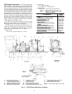
A motor-driven oil pump (Item 10) discharges oil to an oil
cooler/filter (Item 16) at a rate and pressure controlled by an
oil regulator (Item 10). The differential oil pressure (bearing
supply versus oil reservoir) is registered on the control panel.
Water flow through the oil cooler is manually adjusted by
a plug valve (Item 17) to maintain the oil at an operating
temperature of approximately 145 F (63 C). During shut-
down, the oil temperature is also maintained at 150 to
160 F (65 to 71 C) by an immersion heater (Item 7) in order
to minimize absorption of refrigerant by the oil.
Upon leaving the cooler section of the oil cooler/filter, the
oil is filtered (Item 15) and a portion is directed to the seal-
end bearing (Item 1) and the shaft seal (Item 2). The remain-
der lubricates thrust (Item 14) and journal bearings (Item 12).
Thrust bearing temperature is indicated on the PIC controls.
Oil from both circuits returns by gravity to the reservoir.
The shaft seal of the open compressor drive must be kept
full of lubrication oil, even when the chiller is not operating,
to prevent loss of refrigerant.
If the chiller is not operating and the oil pump has not
operated during the last 12 hours, the control system auto-
matically runs the oil pump for one minute in order to keep
the contact seal filled with oil.
IMPORTANT: If the control power is to be deener-
gized for more than one day, the chiller refrigerant should
be pumped over to the economizer/storage vessel.
8