


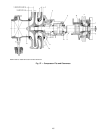
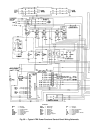
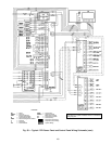
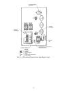

NOTES FOR FIG. 60
I GENERAL
1.0 Starters shall be designed and manufactured in accordance
with Carrier Engineering requirement Z-375.
1.1 Allfield-supplied conductorsand devices,field-installation wir-
ing,and terminationof conductorsand devicesmust bein com-
pliance with all applicable codes and job specifications.
1.2 The routing of field-installed conduit and conductors and the
location offield-installed devicesmust notinterfere with equip-
ment access of the reading, adjusting, or servicing of any
component.
1.3 Equipmentinstallation andall startingand controldevices must
comply with details in equipment submittal drawings and
literature.
1.4 Contacts and switches are shown in the position they would
assume withthe circuitdeenergized and thechiller shutdown.
1.5 WARNING: Do not use aluminum conductors.
1.6 Installer is responsible for any damage caused by improper
wiring between starter and chiller.
II POWER WIRING TO STARTER
2.0 Provide a means of disconnecting power to the starter.
2.1 Power conductor rating must meet minimum unit nameplate
voltage andcompressor motor RLA(ratedload amps).When
3 conductors are used:
Minimum ampacity per conductor = 1.25 x compressor RLA.
When 6 conductors are used:
Minimum ampacityper conductor= 0.721 xcompressor RLA.
2.2 Lug adapters may be required if installation conditions dic-
tate that conductors be sized beyond the minimum ampacity
required. Contact starter supplier for lug information.
2.3 Compressor motor and controls must be grounded by using
equipment grounding lugs provided inside starter enclosure.
III CONTROL WIRING
3.0 Field supplied control conductors to be at least 18 AWG
(American Wire Gage) or larger.
3.1 Chilled water and condenser water flow switch contacts, op-
tional remote start device contacts, and optional spare safety
device contacts must have 24 vdc rating. Maximum current is
60 mA; nominal current is 10 mA. Switches with gold plated
bifurcated contacts are recommended.
3.2 Remove jumper wire between 12A and 12B before connect-
ing auxiliary safeties between these terminals.
3.3 Pilotrelays cancontrol cooler andcondenser pump andtower
fan motor contactor coil loads rated up to 10 amps at 115 vac
or up to 3 amps at 600vac. Control wiring required for Carrier
to start pumps and tower fan motors must be provided to as-
sure chiller protection. If primary pump and tower motor con-
trol is by other means, also provide a parallel means for con-
trol by Carrier. Do not use starter control transformer as the
power source for pilot relay loads.
3.4 Do not route control wiring carrying 30 v or less within a conduit
which has wires carrying 50 v or higher or alongside wires car-
rying 50 v or higher.
3.5 Voltage selector switch in chiller power panel is factory set for
115 v control and oil heater power source. The 230 v position is
not used. If switch is set to 230 v position, oil heater will not
operate.
3.6 Control wiring cables between starter and power panel must be
shielded with minimum rating of 600 v, 80 C. Ground shield at
starter.Starter ManagementModule (SMM)communication cable
must be separate.
3.7 Ifoptional oilpump circuitbreaker isnot supplied withinthe starter
enclosure as shown, it must be located within sight of the chiller
with wiring routed to suit.
3.8 Voltage to terminals LL1 and LL2 comes from a control trans-
former in a starter built to Carrier specifications. Do not connect
anoutside sourceof controlpower tothe compressormotor starter
(terminals LL1 and LL2). An outside power source will produce
dangerous voltage at the line side of the starter, because sup-
plying voltage at the transformer secondary terminals produces
input level voltage at the transformer primary terminals.
4.0 Medium voltage (over 600 volts) compressor motors have 3 ter-
minal connections (lead hooks). Use suitable splice connectors
and insulation for high voltage alternating current cable termi-
nations (these items are not supplied by Carrier). Compressor
motor starter must have nameplate stamped to conform with
Carrier requirement Z-375.
4.1 Powerconductor rating mustmeet minimum unitnameplate volt-
age and compressor motor RLA. (Conductor as defined below
may be a single lead or multiple smaller ampacity leads in par-
allel for the purpose of carrying the equivalent or higher current
of a single larger lead.)
When (3) conductors are used:
Minimum ampacity per conductor = 1.25 × compressor RLA.
4.2 Whenmore thanoneconduit isused torun conductorsform starter
to compressormotor terminalbox, anequal number ofleads from
each phase (conductor) must be in each conduit to prevent ex-
cessive heating (e.g., conductors to motor terminals 1, 2 and 3
in one conduit, and those to 1, 2 and 3 in another.)
4.3 Compressormotor power connectionscan be madethrough top,
top rear, or sides of compressor motor terminal box using holes
cut by contractor to suit conduit. Flexible conduit should be used
for the last few feet to the terminal box for unit vibration isolation.
Use of stress cones may require an oversize (special) motor ter-
minal box (not supplied by Carrier).
4.4 Compressor motor frame to be grounded in accordance with the
National ElectricalCode (NFPA-70) andapplicable codes.Means
for grounding compressor motor is 2 ground pads, 1 each lo-
cated near each motor foot opposite the shaft end.
4.5 Do not allow motor terminals to support weight of wire cables.
Use cable supports and strain reliefs as required.
113