


5. Open the drain located on the shell of the cooler/filter.
Run a hose from the drain to a bucket to catch the oil.
6. Once the pressure has been relieved and the oil drained,
loosen the bolts that hold the cover on the filter body.
Remove the old filter cartridges and replace with a new
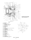
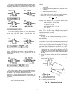
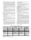
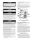
filter cartridge.Assemble the filter assembly (filters, spacer,
and stopper assembly), and make sure that the spring is
centered against the filter assembly as shown in Fig. 44.
7. Replace the drain fitting, using standard practices to en-
sure a leak-tight joint. Evacuate the air from the cooler/
filter assembly.
8. Once the assembly has been evacuated, open the isola-
tion valves.
9. Connect power to the oil heater and oil pump. The oil
heater should turn on and warm the oil to 140 to 150 F
(60 to 66 C). Operate the oil pump for 2 minutes. Add oil,
if required, to keep the level up in the lower sight glass.
Oil should be visible in the reservoir sight glass during all
operating and shutdown conditions.
EXTERNAL GEAR OIL FILTER — Change the oil filter
annually or whenever the chiller is open for repairs. The 17EX
external gear lubrication system has an isolatable filter. Use
the following procedure.
1. Make sure that the compressor is off and the compressor
disconnect is open.
2. Disconnect the power to the oil heater, if equipped, and
to the oil pump.
3. Close the line valves to the filter.
4. Relieve any pressure from within the filter by using the
pressure connection on the oil feed line valve to the com-
pressor. Run a hose from the connection to a bucket to
catch the oil.
5. Open the drain located on the shell of the cooler/filter.
Run a hose from the connection to a bucket to catch the
oil.
6. Once the pressure has been removed and the oil drained,
loosen the bolts that hold the cover on the filter body.
Remove the oil filter cartridges and replace with new car-
tridges. Assemble the filter assembly (filters, spacer, and
stopper assembly), and make sure that the spring is cen-
tered against the filter assembly, as shown in Fig. 44.
7. Replace the drain fitting, using standard practices to en-
sure a leak-tight joint.
8. Open the isolation valves.
9. Connect power to the oil heater, if equipped, and oil pump.
Operate the oil pump for 2 minutes. Add oil, if required,
to keep the level up in the sight glass.
Oil should be visible in the reservoir sight glass during all
operating and shutdown conditions.
Oil Specifications — If oil is to be added, it must meet
the Carrier specifications shown in Table 11.
Oil Changes — Carrier recommends changing the oil
after the first year of operation and every three to five years
thereafter as a minimum. Carrier also recommends a yearly
oil analysis. However, if a continuous oil monitoring system
is functioning and a yearly oil analysis is performed, the time
between oil changes can be extended.
COMPRESSOR OIL
1. Open the control and oil heater circuit breaker.
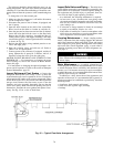
2. Drain the oil reservoir by opening the oil charging valve,
(Fig. 2, Item 22). Slowly open the valve against refrig-
erant pressure.
3. Change the oil filter at this time. See the Changing the
Oil Filters section, page 76.
4. Charge the chiller with approximately 20 gallons (76 L)
of oil for FX (size 531-599) style compressors in order to
bring the level to the middle of the upper sight glass
(Fig. 2, Item 21). Turn on the power to the oil heater and
let the PIC warm it up to at least 140 F (60 C). Operate
the oil pump manually, through the control test, for 2 min-
utes. The oil level should be between the lower sight glass
and one-half full in the upper sight glass for shutdown
conditions.
EXTERNAL GEAR OIL — Proper lubrication is vital to
maintain gear drive performance. After 500 hours or 4 weeks
of initial operation, whichever is first, the external gear drive
should be thoroughly drained, flushed, and refilled with the
proper lubricant. Under normal operating conditions, the lu-
bricant should be changed every 2500 hours or 6 months,
whichever comes first. This change frequency can be ex-
tended if an oil sample analysis indicates a very limited deg-
radation or contamination.
Table 11 — 17EX Chiller Oil Specifications
SPECIFICATION COMPRESSOR
MOTOR SLEEVE
BEARINGS
EXTERNAL
GEAR
PUMPOUT
COMPRESSOR
AND OIL
SEPARATOR
Oil Type* Inhitited Polyolester-Based
Synthetic Compressor Oil
Mineral-Based, Rust and
Oxidation Inhibited Turbine
Grade Oil
Rust and Oxidation
Inhibited Oil
Reciprocating
Compressor Oil
Viscosity at
100 F (37 C)
ISO 68
(300 SSU)
ISO 32
(150 SSU)
ISO 68
(300 SSU)
ISO 68
(300 SSU)
Carrier Part Number PP23BZ107 PP23BZ091 PP23BB005 PP23BZ103
Carrier Specification PP47-12 PP16-0 PP16-2 PP47-31
Recommended
Manufacturer
ICI, Emkarate RL68H Mobil, DTE Light
Texaco, Regal R & 0432
Sun Oil, Sunvis 932
Chevron, GST ISO 32
Mobil Oil, DTE Heavy Medium
Texaco, Regal UR & 068
Chevron, OC #68
NOCO, Turbine T-68
Castrol Icematic SW68
ICI Emkarate RL68HP
Capacity 20 gal (76 L) 0.6 gal (2.3 L) per bearing 17 gal (41.6L) Compressor:
4.5 pints (2.6 L)
Oil Separator:
1 pint (0.6 L)
LEGEND
SSU — Saybolt Universal Seconds
*Oil type specified for chillers using HFC-134a refrigerant.
77