


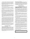
INTRODUCTION
Before initial start-up of the 17EX unit, those involved in
the start-up, operation, and maintenance should be thor-
oughly familiar with these instructions and other necessary
job data. This book is outlined so that you may become fa-
miliar with the control system before performing start-up pro-
cedures. Procedures in this manual are arranged in the se-
quence required for proper chiller start-up and
operation.
This unit uses a microprocessor controlled system. Do
not short or jumper between terminations on circuit boards
or modules; control or board failure may result.
Be aware of electrostatic discharge (static electricity) when
handling or making contact with circuit boards or mod-
ule connections. Always touch a chassis (grounded) part
to dissipate body electrostatic charge before working in-
side the control center.
Use extreme care when handling tools near boards and
when connecting or disconnecting terminal plugs.
Circuit boards can easily be damaged. Always hold boards
by the edges and avoid touching components and
connections.
This equipment uses, and can radiate, radio frequency
energy. If not installed and used in accordance with
the instruction manual, it may cause interference to
radio communications. It has been tested and found to
comply with the limits for a Class A computing device
pursuant to Subpart J of Part 15 of FCC Rules, which
are designed to provide reasonable protection against such
interference when operated in a commercial environ-
ment. Operation of this equipment in a residential area
is likely to cause interference, in which case the user, at
his own expense, will be required to take whatever mea-
sures may be required to correct the interference.
Always store and transport replacement or defective boards
in anti-static shipping bag.
ABBREVIATIONS
Frequently used abbreviations in this manual include:
CCN — Carrier Comfort Network
CCW — Counterclockwise
CHW — Chilled Water
CHWR — Chilled Water Return
CHWS — Chilled Water Supply
CW — Clockwise
ECW — Entering Chilled Water
ECDW — Entering Condenser Water
EMS — Energy Management System
HGBP — Hot Gas Bypass
I/O — Input/Output
LCD — Liquid Crystal Display
LCDW — Leaving Condenser Water
LCW — Leaving Chilled Water
LED — Light-Emitting Diode
LID — Local Interface Device
OLTA — Overload Trip Amps
PIC — Product Integrated Control
PSIO — Processor Sensor Input/
Output Module
RLA — Rated Load Amps
SCR — Silicon Control Rectifier
SMM — Starter Management Module
TXV — Thermostatic Expansion Valve
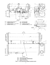
17EX CHILLER FAMILIARIZATION
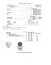
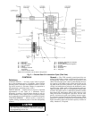
Chiller Identification Label (Fig. 1) —
The iden-
tification label is located on the right side of the chiller con-
trol center panel. The label contains information on model
number, refrigerant charge, rated voltage, etc.
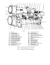
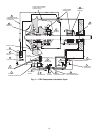
System Components (Fig. 2) — The components
include the cooler and condenser heat exchangers in sepa-
rate vessels, compressor, compressor and gear lubrication pack-
ages, control center, speed increaser economizer/storage vessel,
motor, and starter. The compressor drive consists of an ex-
ternal gear (speed increaser) and an electric motor. All con-
nections from pressure vessels have external threads to en-
able each component to be pressure tested with a threaded
pipe cap during factory assembly.
Cooler — This vessel (also known as the evaporator) is
located underneath the condenser, next to the economizer/
storage vessel. The cooler is maintained at lower tempera-
ture and pressure so that evaporating refrigerant can remove
heat from water flowing through its internal tubes.
Condenser — The condenser operates at a higher tem-
perature and pressure than the cooler and has water flowing
through its internal tubes in order to remove heat from the
refrigerant.
Compressor — This component maintains system tem-
perature and pressure differences and moves the heat-
carrying refrigerant from the cooler to the condenser.
Control Center — The control center is the user inter-
face for controlling the chiller and regulates the chiller ca-
pacity as required to maintain proper leaving chilled
water temperature. The control center:
• registers cooler, condenser, and lubricating system
pressures
• shows chiller operating and alarm shutdown conditions
• records the total chiller operating hours and how many hours
the chiller has been running
• sequences chiller start, stop, and recycle under micro-
processor control
• provides access to other CCN (Carrier Comfort Network)
devices
Motor Starter (Purchased Separately) — The starter
allows the proper start and disconnect of electrical energy
for the compressor-motor, oil pump, oil heater, and control
panels.
Economizer/Storage Vessel — During normal op-
eration, this vessel functions as an economizer, returning flash
gas to the second stage of the compressor and increasing the
efficiency of the refrigeration cycle. During periods of shut-
down and service, the economizer/storage vessel can serve
as a storage tank for the refrigerant.
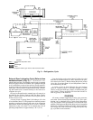
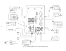
REFRIGERATION CYCLE (Fig. 3)
The 17EX chiller can be used to chill either water or brine.
The data in this book applies to either application. Appli-
cations using corrosive brines may require using special tubes,
tubesheet, and waterbox materials which are special order
items.
5