


Surge Protection — Compressor surge can be de-
tected by the PIC based on operator configured settings. Surge
causes amperage fluctuations of the compressor motor. The
PIC monitors these amperage swings, and if the swing is
greater than the configured setting (SURGE DELTA
PERCENT AMPS) in one second, then one surge event has
occurred. The setting is displayed and configured on the
SERVICE1 screen. Its default setting is 25% amps.
Asurge protection chiller shutdown occurs when the surge
protection counter reaches 12 within an operator specified
time period, known as the surge time period. The
surge protection count (SURGE PROTECTION COUNTS
parameter, Table 2, Example 13) can be monitored on the
MAINT03 screen. The SURGE TIME PERIOD parameter is
displayed and configured on the SERVICE1 screen. See
Table 2, Example 8. It has a default of 2 minutes.
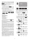
Lead/Lag Control — Lead/lag is a control system pro-
cess that automatically starts and stops a lag or second chiller
in a 2-chiller system. Refer to Fig. 15 and 16 for menu, table,
and screen selection information. On chillers that have PSIO
software with lead/lag capability, it is possible to use the PIC
controls to perform the lead/lag function on 2 chillers. Athird
chiller can be added to the lead/lag system as a standby chiller
to start up if the lead or lag chiller in the system has shut
down during an alarm condition and additional cooling is
required.
NOTE: Lead/lag parameters can be viewed and modified on
the LEAD/LAG CONFIGURATION screen, accessed from
the EQUIPMENT CONFIGURATION table. See Table 2,
Example 7. Lead/lag status during chiller operation is viewed
on the MAINT04 screen, accessed from the CONTROL
ALGORITHM STATUS table. See Table 2, Example 14.
Lead/Lag System Requirements:
• all chillers must have PSIO software capable of perform-
ing the lead/lag function
• water pumps MUST be energized from the PIC controls
• water flows should be constant
• CCN Time Schedules for all chillers must be identical
Operation Features:
• 2 chiller lead/lag
• addition of a third chiller for backup
• manual rotation of lead chiller
• load balancing if configured
• staggered restart of the chillers after a power failure
• chillers may be piped in parallel or in series chilled water
flow
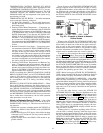
COMMON POINT SENSOR INSTALLATION — Lead/
lag operation does not require a common chilled water point
sensor. Common point sensors can be added to the 8-input
option module, if desired. Refer to the certified drawings for
termination of sensor leads.
NOTE: If the common point sensor option is chosen on a
chilled water system, each chiller should have its own 8-input
option module and common point sensor installed. A chiller
uses its own common point sensor for control when that chiller
is designated as the lead chiller. The PIC cannot read the
value of common point sensors installed on other chillers in
the chilled water system.
When installing chillers in series, use a common point sen-
sor. If a common point sensor is not used, the leaving chilled
water sensor of the upstream chiller must be moved into the
leaving chilled water pipe of the downstream chiller.
If return chilled water control is required on chillers piped
in series, the common point return chilled water sensor should
be installed. If this sensor is not installed, the return chilled
water sensor of the downstream chiller must be relocated to
the return chilled water pipe of the upstream chiller.
To properly control the common supply point temperature
sensor when chillers are piped in parallel, the water flow through
the shutdown chiller(s) must be isolated so there is no water
bypass around the operating chiller. The common point sen-
sor option must not be used if water bypass around the op-
erating chiller is occurring.
CHILLER COMMUNICATION WIRING — Refer to the
chiller Installation Instructions and the Carrier Comfort Net-
work Interface section on page 53 of this manual for infor-
mation on chiller communication wiring.
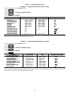
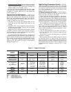
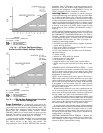
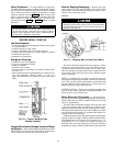
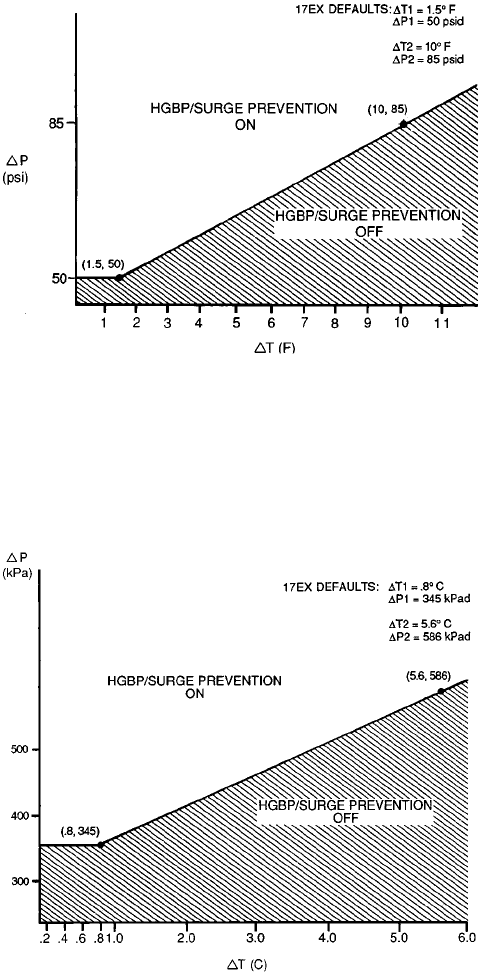
LEGEND
⌬P = (Condenser psi) − (Cooler psi)
⌬T = (ECW) − (LCW)
ECW — Entering Chilled Water
HGBP — Hot Gas Bypass
LCW — Leaving Chilled Water
Fig. 18 — 17EX Hot Gas Bypass/Surge
Prevention With Default Settings (English)
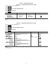
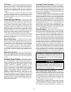
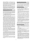
LEGEND
⌬P = (Condenser kPa) − (Cooler kPa)
⌬T = (ECW) − (LCW)
ECW — Entering Chilled Water
HGBP — Hot Gas Bypass
LCW — Leaving Chilled Water
Fig. 19 — 17EX Hot Gas Bypass/Surge Prevention
With Default Settings (SI)
38