


5. After the last digit is changed, the LID goes to the
BUS # parameter. Press the EXIT
softkey to leave the
screen, record your password change, and return to the
SERVICE menu.
BE SURE TO REMEMBER YOUR PASSWORD.
Retain a copy of the password for future reference.
If you forget your password, you will not be able to
access the SERVICE menu unless you install and
download a new PSIO module.
INPUT TIME AND DATE — Access the Time and Date
table on the SERVICE menu. Input the present time of day,
date, and day of the week. HOLIDAY TODAY should only
be configured to YES if the present day is a holiday.
CHANGE THE LID CONFIGURATION IF NECESSARY
— From the LID CONFIGURATION screen, the LID CCN
address, units (English or SI), and password can be changed.
If there is more than one chiller at the jobsite, change the
LID address on each chiller so that each chiller has its own
address. Note and record the new address. Change the screen
to SI units as required, and change the password if desired.
To Change the LID Display From English to Metric Units
— By default, the LID displays information in English units.
To change to metric units:
1. Press the MENU and SERVICE softkeys. Enter your pass-
word and highlight LID CONFIGURATION. Press the
SELECT softkey.
2. Use the ENTER softkey to scroll to US IMP/METRIC.
3. Press the softkeys that correspond to the units you want
displayed on the LID (e.g., US or METRIC ).
MODIFY CONTROLLER IDENTIFICATION IF NECES-
SARY — The PSIO module address can be changed from
the CONTROLLER IDENTIFICATION screen. If there is
more than one chiller at the site, change the controller ad-
dress for each chiller. Write the new address on the PSIO
module for future reference.
INPUT EQUIPMENT SERVICE PARAMETERS IF NEC-
ESSARY— The EQUIPMENT SERVICE table has 3 screens:
SERVICE1, SERVICE2, and SERVICE3.
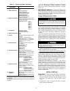
Configure SERVICE1 Table — Access the SERVICE1 table
to modify or view the following:
Chilled Medium Water or Brine?
Brine Refrigerant Trippoint Usually 3° F (1.7° C) below design
refrigerant temperature
Surge Limiting or
Hot Gas Bypass Option
Is HGBP installed?
Minimum Load Points
(T1/P1)
Per job data — See Modify Load
Points section
Full Load Points
(T2/P2)
Per job data — See Modify Load
Points section
Motor Rated Load Amps Per job data
Motor Rated Line Voltage Per job data
Motor Rated Line kW Per job data (if kW meter installed)
Line Frequency 50 or 60 Hz
Compressor Starter Type Reduced voltage or full?
Stop-to-Start Timer Follow motor vendor recommenda-
tion for time between starts. See
certified prints for correct value.
NOTE:Other valuesareleftat thedefaultvalues.Thesemay bechanged
by the operator as required. SERVICE2 and SERVICE3 tables can
be modified by the owner/operator as required.
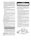
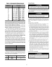
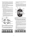
Modify Minimum and Maximum Load Points (⌬T1/P1;
⌬ T2/P2) If Necessary —These pairs of chiller load points,
located on the SERVICE1 table, determine when to limit guide
vane travel or to open the hot gas bypass valve when surge
prevention is needed. These points should be set based on
individual chiller operating conditions.
If, after configuring a value for these points, surge pre-
vention is operating too soon or too late for conditions, these
parameters should be changed by the operator.
Example of configuration:
Chiller operating parameters:
Refrigerant used: HFC-134a
Estimated Minimum Load Conditions:
44 F (6.7 C) LCW
45.5 F (7.5 C) ECW
43 F (6.1 C) Suction Temperature
70 F (21.1 C) Condensing Temperature
Estimated Maximum Load Conditions:
44 F (6.7 C) LCW
54 F (12.2 C) ECW
42 F (5.6 C) Suction Temperature
98 F (36.7 C) Condensing Temperature
Calculate Maximum Load — To calculate the maximum load
points, use the design load condition data. If the chiller full
load cooler temperature difference is more than 15° F
(8.3° C), estimate the refrigerant suction and condensing tem-
peratures at this difference. Use the proper saturated pres-
sure and temperature for the particular refrigerant used.
Suction Temperature:
42 F (5.6 C) = 37 psig (255 kPa) saturated
refrigerant pressure (HFC-134a)
Condensing Temperature:
98 F (36.7 C) = 120 psig (1827 kPa) saturated
refrigerant pressure (HFC-134a)
Maximum Load ⌬T2:
54 – 44 = 10° F (12.2 – 6.7 = 5.5° C)
Maximum Load ⌬P2:
120 – 37 = 83 psid (827 – 255 = 572 kPad)
To avoid unnecessary surge prevention, add about 10 psid
(70 kPad) to ⌬P2 from these conditions:
⌬T2 = 10° F (5.5° C)
⌬P2 = 93 psid (642 kPad)
Calculate Minimum Load — To calculate the minimum load
conditions, estimate the temperature difference that the cooler
will have at 20% load, then estimate what the suction and
condensing temperatures will be at this point. Use the proper
saturated pressure and temperature for the particular refrig-
erant used.
Suction Temperature:
43 F (6.1 C) = 38 psig (262 kPa) saturated
refrigerant pressure (HFC-134a)
Condensing Temperature:
70 F (21.1 C) = 71 psig (490 kPa) saturated
refrigerant pressure (HFC-134a)
Minimum Load ⌬T1 (at 20% Load):
2° F (1.1° C)
Minimum Load ⌬P1:
71 – 38 = 33 psid (490 – 262 = 228 kPad)
Again, to avoid unnecessary surge prevention, add 20 psid
(140 kPad) at ⌬P1 from these conditions:
⌬T1 = 2° F (1.1° C)
⌬P1 = 53 psid (368 kPad)
55