


NOTE: The LID does not automatically re-attach to the PSIO
module on the chiller.Access the ATTACH TO NETWORK
DEVICE table, scroll to LOCAL, and press the
ATTACH
softkey to upload the local device. The software
for the local chiller will now be uploaded.
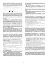
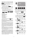
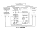
Service Operation — Figure 16 shows an overview of
the service menu.
TO ACCESS THE SERVICE SCREENS
1. On the MENU screen, press the SERVICE
softkey. The
softkeys now correspond to the numerals 1, 2, 3, and 4.
NOTE: The factory-set password is1-1-1-1.Seethe
Input Service Configurations section, page 54, for informa-
tion on how to change a password.
2. Press the four digits of your password, one at a time. An
asterisk (*) appears as you enter each digit.
If the password is incorrect, an error message is dis-
played. If this occurs, return to Step 1 and try to access
the SERVICE tables again. If the password is correct, the
softkey labels change to NEXT
, PREVIOUS ,
SELECT
, and EXIT , and the LID screen displays the
following SERVICE tables:
• Alarm History
• Control Test
• Control Algorithm Status
• Equipment Configuration
• Equipment Service
• Time and Date
• Attach to Network Device
• Log Out of Device
• Controller Identification
• LID Configuration
See Fig. 16 for additional screens and tables available form
the SERVICE tables listed above. Use the EXIT
softkey to
return to the MENU screen.
TO LOG OFF — Access the LOG OUT OF DEVICE table
from the SERVICE menu. The LID exits the SERVICE menu.
To re-enter the SERVICE menu, you must re-enter your pass-
word as described above.
NOTE: To prevent unauthorized persons from accessing the
LID service screens, the LID automatically signs off and
password-protects itself if a key has not been pressed for
15 minutes. The sequence is as follows. Fifteen minutes af-
ter the last key is pressed, the default screen displays, the
LID screen light goes out (analogous to a screen saver), and
the LID logs out of the password-protected SERVICE menu.
Other screens and menus, such as the STATUS screen can
be accessed without the password by pressing the appropri-
ate softkeys.
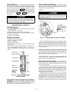
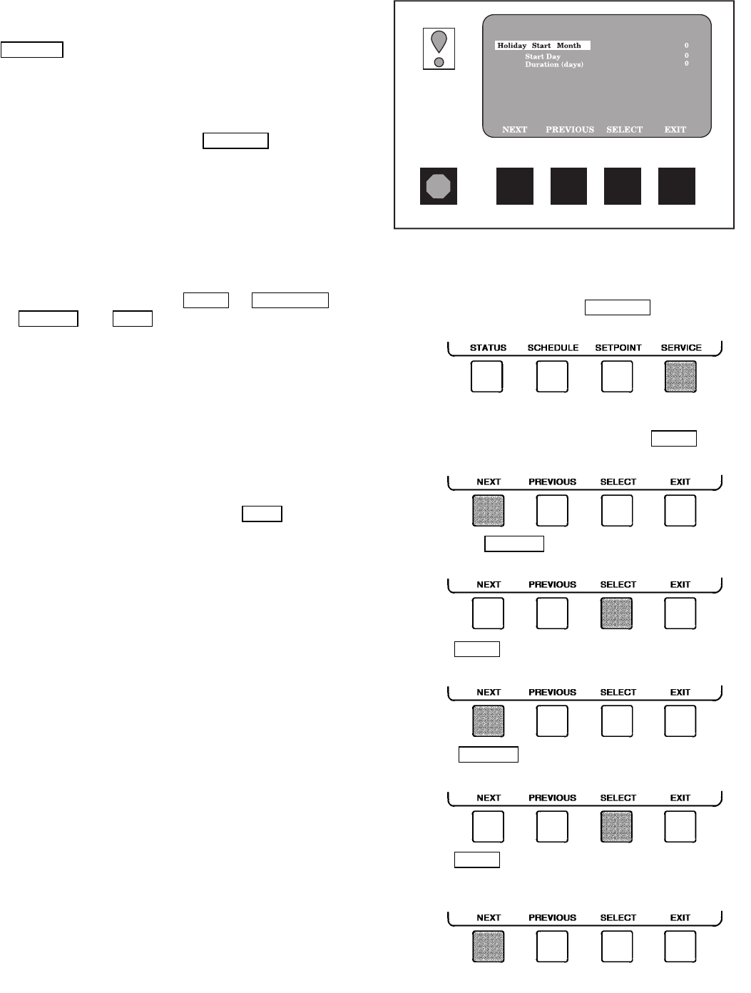
HOLIDAY SCHEDULING (Fig. 21) — The time schedules
may be configured for special operation during holiday pe-
riods. When modifying a time period, an ‘‘H’’ at the end of
the days of the week field signifies that the period is appli-
cable to a holiday. (See Fig. 14.)
The broadcast function must be activated for the holidays
configured on the HOLIDEF screen to work properly. Ac-
cess the BRODEF screen from the EQUIPMENT CON-
FIGURATION table and set the parameter that activates the
BRODEF function to YES. Note that, when the chiller is
connected to a CCN network, only one chiller or CCN de-
vice can be configured to be the broadcast device. The con-
troller that is configured to be the broadcaster is the device
responsible for transmitting holiday, time, and daylight-
savings dates throughout the network.
To view or change the holiday periods for up to 18 dif-
ferent holidays, perform the following operation:
1. At the Menu screen, press SERVICE
to access the
SERVICE menu.
2. If not logged on, follow the instructions for entering your
password. See the section, To Access the Service Screens,
page 42. Once logged on, press NEXT until
EQUIPMENT CONFIGURATION is highlighted.
3. Press the SELECT softkey to access the EQUIP-
MENT CONFIGURATION tables.
4. Press NEXT until HOLIDEF is highlighted. This is
the holiday definition table.
5. Press SELECT to access the HOLIDEF screen.
This screen lists 18 holiday tables.
6. Press NEXT to highlight the holiday table that you
wish to view or change. Each table is one holiday pe-
riod, starting on a specific date, and lasting up to 99 days.
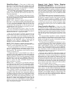
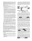
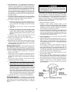
EF, EX, FA CHLR HOLDY01S CONFIGURATION SELECT
Fig. 21 — Example of Holiday Period Screen
42