


9. Place a clean, lint-free cloth on a smooth, sturdy work
surface. Place the seal housing assembly on the cloth
with the face of the contact sleeve in contact with the
cloth. While one person pushes down on the housing to
compress the spring, another person must remove the
snap ring. Then, slowly let the seal housing rise until
the spring is fully extended.
10. Remove Items 2B and 12 (O-rings).
11. Slide the outer carbon ring (Item 19) off the shaft.
12. Remove the lubricating tube (Item 1) and gasket
(Item 24).
13. Remove the inner carbon key (Item 36).
14. Remove the inner seal retaining screws (Item 23) and
the diaphragm retainer (Item 22).
15. Using a spanner wrench, loosen the lock nut (Item 15).
The lock nut has a right-hand thread. Remove the lock
nut. The inner seal spring (Item 27) may push the con-
tact ring part way out as the lock nut is loosened.
16. Carefully slide the rotating contact ring (Item 21) off
the shaft. The ring slips onto the shaft with a very close
tolerance and is prone to sticking. Slide it slowly to avoid
a tight jam. To release, tap gently with a SOFT hammer.
17. Remove O-ring (Item 14). This O-ring will be crushed
into a triangular shape. Since it is not an ordinary O-ring
gland, this is normal. Always replace with a new O-ring.
18. The seal gland sleeve (Item 29) can be removed, but it
is generally not necessary to do so. If the seal gland is
removed, make sure it is reinstalled with the bevel (that
contains the O-ring) facing outward.
19. The inner carbon ring (Item 26), the diaphragm
(Item 25), the inner carbon guide ring (Item 34), and the
inner seal spring (Item 27) can be removed as an as-
sembly. The carbon ring is held to the guide ring by raised
barbs on the guide ring. Carefully pull the carbon ring
from the guide ring. The diaphragm can now be re-
moved from the guide ring. Inspect the diaphragm for
wear.
20. To remove the inner seal retainer (Item 28) and O-ring
(Item 35), use 4 screws (Item 23) in the 4 threaded holes
spaced evenly around the seal retainer to jack the part
out of position.
If the inner seal shims are damaged, carefully measure them
so that a shim package of the same thickness can be in-
stalled. The thickness ofthe shim package should not be changed
unless the compressor shaft and/or thrust bearing are re-
placed. Replacing either of these items could affect the float
of the inner seal. This float is adjusted by varying the thick-
ness of the shim pack.
This completes the disassembly of the seal.
Clean all parts to be reused with solvent, coat with oil and
place in a protected area until needed.
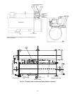
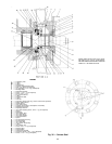
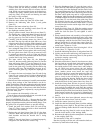
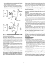
SEAL REASSEMBLY (Fig. 36) — Be sure that all gasket
surfaces are clean and that all holes, including oil holes, are
properly aligned between the gasket and mating flange. Coat
the gasket with oil-graphite mixture to prevent sticking.
1. Install the inner seal retainer (Item 28) and O-ring
(Item 35). Then, remove the bolts to allow installation
of the inner seal assembly.
2. Replace the seal gland sleeve (Item 29) if it has been
removed. Make sure that the plain side is against the
shaft shoulder and that the beveled side is facing
outward.
NOTE: If the seal gland sleeve is oriented improperly,
refrigerant will leak under the contact ring.
3. Place the diaphragm (Item 25) over the inner seal re-
tainer (Item 28). With the best lapped sealing face of the
carbon away from the diaphragm and the notch for the
key centered between two of the bolt holes in the dia-
phragm, gently push the inner carbon ring (Item 26) into
the inner carbon guide ring until it is tight against the
diaphragm. Make sure that the diaphragm is not wrinkled
or folded between the carbon and the retainer. Place the
spring (Item 27) over the back of the guide ring. Place
this assembly into the seal, and make sure that the car-
bon face can travel a minimum of 0.06 inches (1.5 mm)
in each direction from the outside edge of the seal gland
sleeve (Item 29).
4. Install the O-ring (Item 14). Slide the rotating contact
ring (Item 21) into position against the seal gland sleeve.
Install the lock nut (Item 15) and tighten it with a
spanner.
5. Gently rotate the inner seal assembly to line up the bolt
holes in the diaphragm with the bolt holes in the inner
seal retainer (Item 28). Place the diaphragm retainer over
the diaphragm with the beveled side toward the dia-
phragm. Install the 14 one-inch long screws (Item 23),
leaving the top 2 holes on either side of the notch in the
carbon open. Tighten to 2 ft-lb.
6. Install the inner carbon key (Item 36) using the 1-1/4-in.
screws (Item 37). Tighten to 2 ft-lb.
7. Install the lubricating tube (Item 1) and gasket (Item 24).
8. Lightly coat the outer carbon ring with compressor oil.
Then, slide the outer carbon ring (Item 19) into position
against the rotating contact ring.
9. Install O-ring (Item 12).
10. Place the contact sleeve (Item 18) face down on a clean,
lint-free cloth on a smooth, hard, work surface, and place
the contact sleeve spring over the sleeve. Lightly coat
the outside surface of the contact sleeve with compres-
sor oil. While one person places the seal housing
(Item 3) over the contact sleeve and presses the spring
down, another person must install the snap ring
(Item 16) in the groove around the small end of the con-
tact sleeve. Once the snap ring is firmly seated in the
groove, slowly let the seal housing rise until the snap
ring rests against the housing. Rotate the sleeve in the
seal housing until the key slot in the sleeve is in line
with the bolt hole for the contact sleeve key (Item 11).
11. Install the O-ring (Item 2B) into its groove, and place
the seal housing into position on the compressor. Guide
rods can help accomplish this task. Place the coupling
guard mounting ring (Item 4) over the seal housing, and
fasten both in place with 8 hex-head bolts (Item 6). Draw
in the housing against the seal spring by tightening the
bolts in steps in a crisscross pattern to draw the housing
evenly.
12. Once the bolts have been tightened, remove the snap
ring from the contact sleeve, and set it aside.
13. Install the contact sleeve key (Item 11).
14. Install the shaft end labyrinth (Item 8) and the windage
baffle using screws (Item 9). The split lines of the laby-
rinth and windage baffle should be located 90 degrees
apart.
15. Mount the snap ring (Item 16) on the screws (Item 41)
near the inside surface of the windage baffle.
16. Reconnect the tubing from the atmospheric oil chamber
to the coupling (Item 20).
The reassembly of the seal is complete.
Run the oil pump to fill the seal, and rotate the shaft sev-
eral times by hand before leak testing.
70