


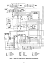
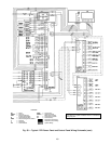
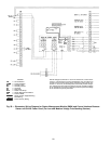
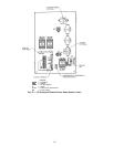
LEGEND
CB — Circuit Breaker
COMM — Communications
N.O. — Normally Open
N.C. — Normally Closed
O.L. — Overload
PR — Pilot Relay
RLA — Rated Load Amps
SMM — Starter Management Module
TB — Terminal Block
Starter Vendor Supplied Wiring
Field Wiring
Carrier Factory Wiring
NOTE: Voltage to terminals LL1 and LL2 comes from a control trans-
former in a starter built to Carrier specifications. Do not connect an
outside source of control power to the compressor motor starter (ter-
minals LL1 and LL2). An outside power source will produce danger-
ous voltage at the line side of the starter, because supplying voltage
at the transformer secondary terminals produces input level voltage
at the transformer primary terminals.
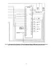
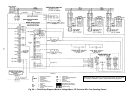
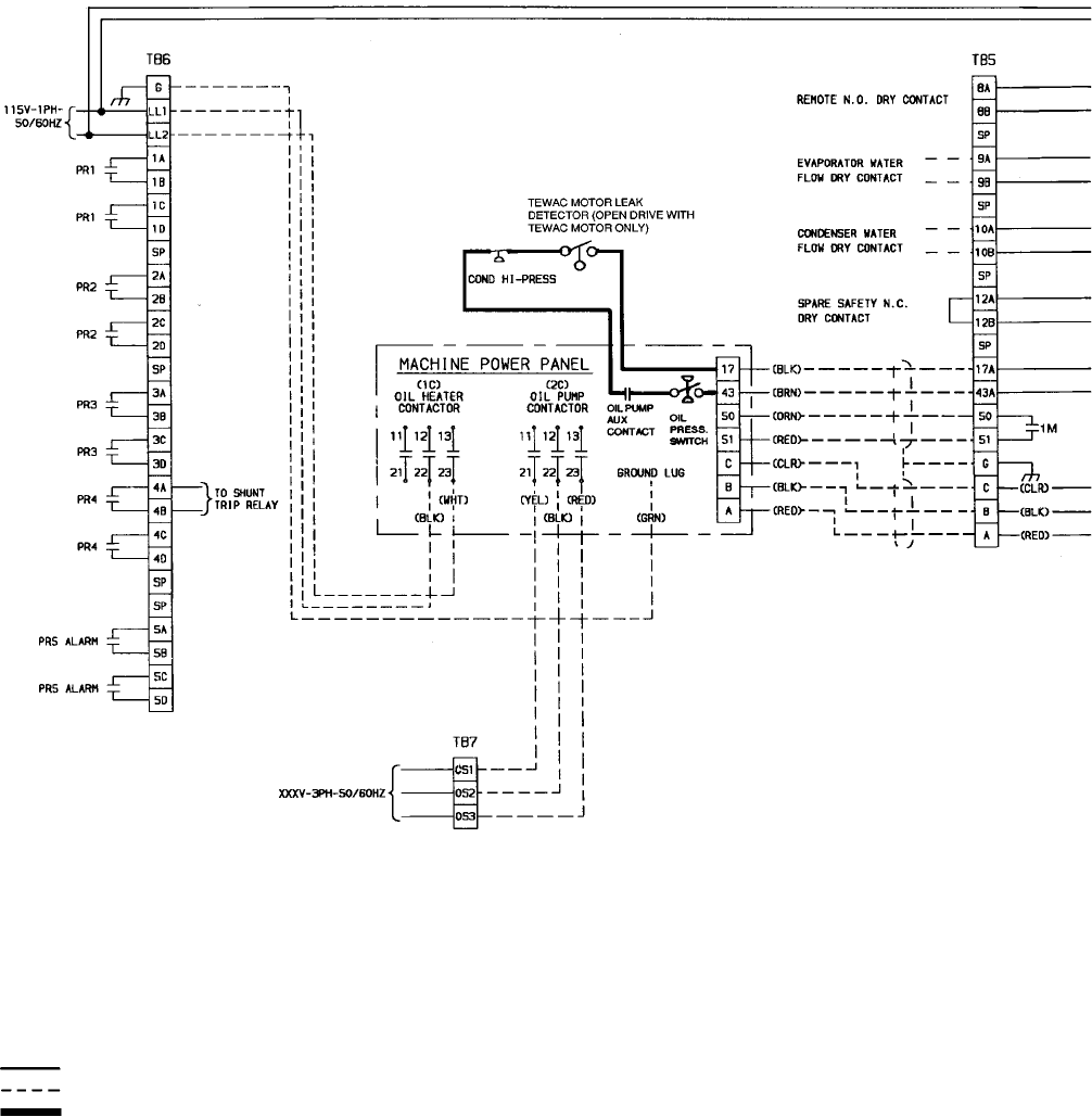
Fig. 59 — Elementary Wiring Diagram for Starter Management Module (SMM) and Control Interface Between
Starter and Chiller Power Panel (For Low and Medium Voltage Free-Standing Starters)
110