


Water must be within design flow limits, clean, and treated
to ensure proper chiller performance and reduce the po-
tential of tube damage due to corrosion, scaling, ero-
sion, and algae. Carrier assumes no responsibility for
chiller damage resulting from untreated or improperly
treated water.
Inspect the Starting Equipment — Before work-
ing on any starter, shut off the chiller, and open all discon-
nects supplying power to the starter.
The disconnect on the starter front panel does not de-
energize all internal circuits. Open all internal and re-
mote disconnects before servicing the starter.
Never open isolating knife switches while equipment is
operating. Electrical arcing can cause serious injury.
Inspect the starter contact surfaces for wear or pitting on
mechanical-type starters. Do not sandpaper or file silver-
plated contacts. Follow the starter manufacturer’s instruc-
tions for contact replacement, lubrication, spare parts
ordering, and other maintenance requirements.
Periodically vacuum or blow off accumulated debris on
the internal parts with a high-velocity, low-pressure blower.
Power connections on newly installed starters may relax
and loosen after a month of operation. Turn power off and
retighten. Recheck annually thereafter.
Loose power connections can cause voltage spikes, over-
heating, malfunctioning, or failures.
Check Pressure Transducers — Prior to start-up
and once a year, the pressure transducers should be checked
against a pressure gage reading. Check all three transducers:
oil pressure, condenser pressure, and cooler pressure.
Note the evaporator and condenser pressure readings on
the STATUS01 screen on the LID. Attach an accurate set of
refrigeration gages to the cooler and condenser Schrader fit-
tings. Compare the two readings. If there is a difference in
readings, the transducer can be calibrated, as described in
the Troubleshooting Guide section.
Pumpout System Maintenance — For compres-
sor maintenance details, refer to the 06D, 07D Installation,
Start-Up, and Service Instructions.
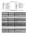
OPTIONAL PUMPOUT COMPRESSOR OIL CHARGE —
Use oil conforming to Carrier specifications for reciprocat-
ing compressor usage. See Table 11.
Oil should be visible in the compressor sight glass both
during operation and at shutdown. Always check the oil
level before operating the compressor. Before adding or chang-
ing oil, relieve the refrigerant pressure as follows:
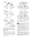
1. Attach a pressure gage to the gage port of either com-
pressor service valve (Fig. 34).
2. Close the suction service valve and open the discharge
line to the storage tank or the chiller.
3. Operate the compressor until the crankcase pressure drops
to 2 psig (13 kPa).
4. Stop the compressor and isolate the system by closing
the discharge service valve.
5. Slowly remove the oil return line connection. Add oil as
required.
6. Replace the connection and reopen the compressor serv-
ice valves.
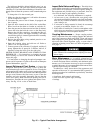
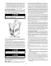
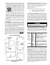
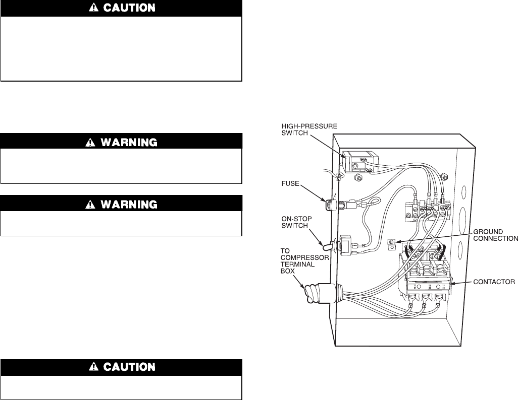
PUMPOUT SAFETY CONTROL SETTINGS (Fig. 47) —
The pumpout system high-pressure switch should open at
161 psig (1110 kPa) and close at 130 psig (896 kPa). Check
the switch setting by operating the pumpout compressor and
slowly throttling the pumpout condenser water.
Ordering Replacement Chiller Parts — When or-
dering Carrier specified parts, the following information must
accompany an order:
• chiller model number and serial number
• name, quantity, and part number of the part required
• delivery address and method of shipment
MOTOR REPLACEMENT PARTS — Replacement or re-
newal parts information for the motor and any auxiliary de-
vices can be obtained from the nearest Westinghouse Motor
Company sales office. A complete description of the needed
part(s) is necessary, together with the complete motor name-
plate reading for positive motor identification.
EXTERNAL GEAR REPLACEMENT PARTS — Replace-
ment or renewal parts information for the external gear and
any auxiliary devices can be obtained from the nearest Nut-
tall or Lufkin sales office. Acomplete description of the needed
part(s) is necessary, together with the complete gear name-
plate reading for positive identification.
TROUBLESHOOTING GUIDE
Overview —
The PIC has many features to help the op-
erator and the technician troubleshoot a 17EX chiller.
• By using the LID display, the actual operating conditions
of the chiller can be viewed while the unit is running.
• The CONTROL ALGORITHM STATUS table includes
screens with information that can be used to diagnose prob-
lems with chilled water temperature control, chilled water
Fig. 47 — Controls for Optional Pumpout
Compressor
83