


Transferring Refrigerant into the Cooler/
Condenser/Compressor Section —
These steps de-
scribe how to transfer refrigerant from the economizer/
storage vessel into the cooler/condenser/compressor section.
This is normally done to prepare for service work on the
economizer/storage vessel.
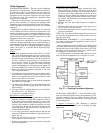
1. Isolate and push refrigerant into the cooler/condenser/
compressor section:
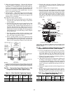
a. Valve positions:
VALVE 1 2 3 4 5 6 7 8 9 10 11
CONDITION CCCCCC
b. Turn off chiller water pumps and pumpout condenser
water.
c. Turn on the pumpout compressor to push refrigerant
out of the economizer/storage vessel.
d. When all liquid refrigerant is out of the economizer/
storage vessel, close the cooler isolation valve 7.
e. Turn off the pumpout compressor.
2. Evacuate refrigerant from the economizer/storage vessel.
a. Access the CONTROL TEST table on the LID. Select
the PUMPDOWN LOCKOUT screen. From this screen,
turn on the chiller water pumps and monitor vessel
pressures.
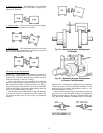
b. Valve positions: Close valves 3 and 4, open valves 2
and 5.
VALVE 1 2 3 4 5 6 7 8 9 10 11
CONDITION CC CCCC C
c. Turn on the pumpout condenser water.
d. Run the pumpout compressor until the suction reaches
15 in. Hg (50 kPa abs). Monitor pressures on the LID
and on refrigerant gages.
e. Close valve 6.
f. Turn off the pumpout compressor.
g. Close valves 1, 2, and 5 (all valves are now closed).
h. Turn off the pumpout condenser water.
i. From the CONTROL TEST table on the LID, turn off
the chiller water pumps and lock out the chiller com-
pressor from operation.
Return Chiller to Normal Operating Conditions
1. Be sure that the vessel that was opened has been evacu-
ated and dehydrated.
2. Access the CONTROL TEST table. From this table, se-
lect the TERMINATE LOCKOUT function to view the
vessel pressures and to turn on chiller water pumps.
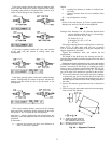
3. Open valves 1, 3, and 6.
VALVE 1234567891011
CONDITION CCCCCCCC
4. Slowly open valve 5, gradually increasing pressure
in the evacuated vessel to 35 psig (141 kPa)
for HFC-134a. Feed refrigerant slowly to prevent
freeze-up.
5. Perform a leak test at 35 psig (141 kPa).
6. Open valve 5 fully. Let the vessel pressures equalize.
VALVE 1 2 3 4 5 6 7 8 9 10 11
CONDITION C C CCCC C
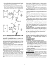
7. Open valves 9 and 10.
8. Open valve 7 to equalize liquid refrigerant levels.
9. Close valves 1, 3, 5, and 6.
VALVE 1234567891011
CONDITION CCCCCC C C
10. Continue to use the TERMINATE/LOCKOUT function
on the LID to turn off water pumps and enable the com-
pressor to operate.
GENERAL MAINTENANCE
Refrigerant Properties —
Refrigerant HFC-134a is
the standard refrigerant in the 17EX.At normal atmospheric
pressure, HFC-134a boils at −14 F (−25 C) and must, there-
fore, be kept in pressurized containers or storage tanks. The
refrigerant is practically odorless when mixed with air. This
refrigerant is non-combustible at atmospheric pressure. Read
the Material Safety Data Sheet (MSDS) and the latest ASHRAE
Safety Guide for Mechanical Refrigeration to learn more about
safe handling of this refrigerant.
Refrigerant HFC-134a will dissolve oil and some non-
metallic materials, dry the skin, and, in heavy concen-
trations, may displace enough oxygen to cause asphyxi-
ation. When handling this refrigerant, protect the hands
and eyes and avoid breathing fumes.
Adding Refrigerant — Follow the procedures de-
scribed in Charge Refrigerant into Chiller section, page 57.
Use the PUMPDOWN LOCKOUT function on the CON-
TROL TEST table to turn on the chiller water pumps
and lock out the compressor when transferring refrig-
erant. Liquid refrigerant may flash into a gas and cause
possible freeze-up when the chiller pressure is below
30 psig (207 kPa) for HFC-134a. If the water pumps are
not controlled by the PIC, they must be controlled
manually.
Removing Refrigerant — When the optional pump-
out system is used, the 17EX refrigerant charge may be trans-
ferred into the economizer/storage vessel or another storage
vessel. Follow procedures in the Pumpout and Refrigerant
Transfer Procedures section when removing or transferring
refrigerant.
Adjusting the Refrigerant Charge — If it is nec-
essary to add or remove refrigerant to improve chiller per-
formance, follow the procedures under theTrimmingRefrigerant
Charge section.
Refrigerant Leak Testing — Because HFC-134a is
above atmospheric pressure at room temperature, leak test-
ing can be performed with refrigerant in the chiller. Use an
electronic detector, soap bubble solution, or ultra-sonic leak
detector. To keep false readings to a minimum, be sure that
the room is well ventilated and free from concentration of
refrigerant. Before making any necessary repairs to a leak,
transfer all refrigerant from the leaking vessel.
Leak Rate — The ASHRAE recommendation is that chill-
ers should be immediately taken off line and repaired if the
refrigerant leak rate for the entire chiller is more than 10%
of the operating refrigerant charge per year.
Additionally, Carrier recommends that leaks totalling less
than the above rate but more than a rate of 1 lb (0.5 kg) per
year should be repaired during annual maintenance or when-
ever the refrigerant is pumped over for other service work.
Test After Service, Repair, or Major Leak — If
all refrigerant has been lost or if the chiller has been opened
for service, the chiller or the affected vessels must be pres-
sure and leak tested. Refer to the Leak Test Chiller section
(page 46) to perform a leak test.
67