


WEEKLY MAINTENANCE
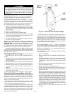
Check the Lubrication System —
Mark the oil level
on the compressor reservoir sight glass, and observe the level
each week while the chiller is shut down.
If the level goes below the lower sight glass, the oil re-
claim system will need to be checked for proper operation.
If additional oil is required, add oil as follows:
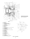
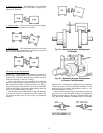
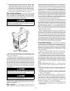
Oil may be added through the oil drain and charging valve
(Fig. 2, Item 22) using a pump. However, an oil charging
elbow on the seal-oil return chamber (Fig. 4) allows oil to be
added without pumping. The seal oil return pump automati-
cally transfers the oil to the main oil reservoir. A pump is
required for adding oil against refrigerant pressure. The oil
charge is approximately 20 gallons (76 L) for FX (size 531-
599) style compressors. The added oil must meet Carrier’s
specifications. Refer to Changing the Oil Filters and Oil Changes
sections. Any additional oil that is added should be logged
by noting the amount and date. Any oil that is added due to
oil loss that is not related to service will eventually return to
the sump, and must be removed when the level is high.
An oil heater is controlled by the PIC to maintain oil tem-
perature above 150 F (65.5 C) or refrigerant temperature plus
70° F (38.9° C) (see the Controls section) when the com-
pressor is off. The LID STATUS02 screen displays whether
the heater is energized or not (OIL HEATER RELAY). If the
PIC shows that the heater is ON, but the sump is not heating
up, the power to the oil heater may be off or the oil level
may be too low. Check the oil level, the oil heater contactor
voltage, and oil heater resistance.
The PIC does not permit compressor start-up if the oil tem-
perature is too low. The PIC continues with start-up only
after the temperature is within limits.
After the initial start or a 3-hour power failure, the PIC
allows the chiller to start once the oil is up to proper tem-
perature, but uses a slow ramp load rate of 2° F (1.6° C) per
minute.
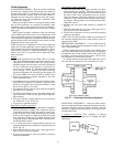
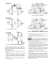
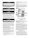
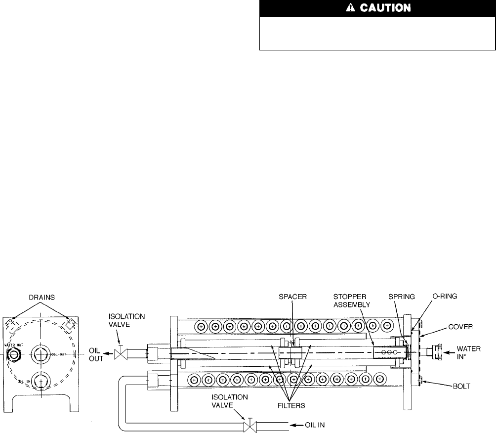
Be sure that the isolation valves on the oil line near the
filter(s) (Fig. 44) are fully open before operating the com-
pressor.
There are no lubrication requirements for the FX disc
coupling.
Check the oil level in the gear reservoir and observe the
level each week. If additional oil is required, add oil as de-
scribed in the Oil Changes section on page 77. The added oil
must meet Carrier specifications. (See Table 11.) Do not over-
fill the reservoir.Any additional oil added or removed should
be logged by noting the amount and date.
Check the oil level in the motor bearings and observe the
level each week. If additional oil is required, add oil as de-
scribed in the Oil Changes section on page 77. The added oil
must meet Carrier specifications. (See Table 11.) Any addi-
tional oil added or removed should be logged by noting the
amount and date.
SCHEDULED MAINTENANCE
Establish a regular maintenance schedule based on the ac-
tual chiller requirements such as chiller load, run hours, and
water quality. The time intervals listed in this section are of-
fered as guides to service only.
Service Ontime — The LID displays a SERVICE ON-
TIME value on the STATUS01 screen. This value should
be reset to zero by the service person or the operator each
time major service work is completed so that time span be-
tween service can be tracked and viewed.
Inspect the Control Center — Maintenance is lim-
ited to general cleaning and tightening of connections. Vacuum
the cabinet to eliminate dust build-up. If the chiller controls
malfunction, refer to the Troubleshooting Guide section for
control checks and adjustments.
Be sure power to the control center is off when
cleaning and tightening connections inside the control
center.
Check Safety and Operating Controls Monthly
—
To ensure chiller protection, the automated control test
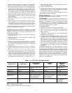
should be done at least once per month. See Table 3 for safety
control settings.
Changing the Oil Filters
COMPRESSOR OIL FILTER — Change this oil filter an-
nually or whenever the chiller is open for repairs. The 17FX
compressor has an isolatable filter so that the filter may be
changed without removing refrigerant from the chiller. Use
the following procedure.
1. Make sure the compressor is off and that the compressor
disconnect is open.
2. Disconnect the power to the oil heater and oil pump.
3. Close the valves to the filter.
4. Relieve the pressure from within the filter by using the
pressure connection on the oil feed line valve to the com-
pressor. Run a hose from the connection to a bucket to
catch the oil.
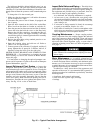
*Water out line is hidden behind oil out line.
Fig. 44 — Typical Compressor or Gear Oil Cooler/Filter
76