


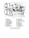
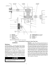
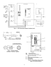
External Gear Lubrication Cycle (Refer to Item
numbers shown in Fig. 5) —
Oil reservoir is con-
tained in the gear base. The external gear oil pump is mounted
below the gear with the cooler/filter. Oil is pumped through
an oil cooler/filter to remove heat and any foreign particles.
A portion of the oil is directed to the gear bearings and gear
mesh spray. The remainder is bypassed to the sump. The bear-
ing and transmission oil returns directly to the reservoir to
complete the cycle.
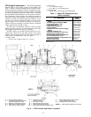
Oil may be charged into the external gear oil reservoir as
described in the section, External Gear Pre-Start Checks,
page 51. Observe the oil level in the oil level glass (Item 4)
on the reservoir wall.
A motor driven oil pump (Item 10) discharges oil to the
oil cooler/filter (Item 12). The pump has an internal pressure
regulator to protect the pump in the event of an obstruction
downstream. Water flow through the oil cooler is manually
adjusted by a plug valve (Item 14) to maintain the oil at an
operating temperature of approximately 130 F (54 C).
Upon leaving the cooler section (Item 13) of the oil cooler/
filter, the oil is filtered (Item 11) and is directed to the pres-
sure control valve (Item 7). Before entering the pressure control
valve, the oil pressure (Item 16) and temperature (Item 8)
are monitored by the PIC.
A portion of the oil then lubricates the gear bearings
(Item 2). Another portion is directed through an orifice
(Item 5) to the gear mesh spray (Item 3) to lubricate the gear
mesh (Item 1) during operation. Oil from both circuits re-
turns by gravity to the reservoir.
STARTERS
All starters, whether supplied by Carrier or the customer,
must meet Carrier Starter Specification Z-375. This speci-
fication can be obtained from a Carrier Sales Representa-
tive. The purpose of this specification is to ensure the com-
patibility of the starter and the chiller. Many styles of compatible
starters are available, including solid-state , auto-transformer,
full-voltage, and, in the case of low-voltage main power sup-
ply, wye-delta closed transition.
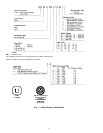
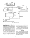
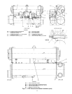
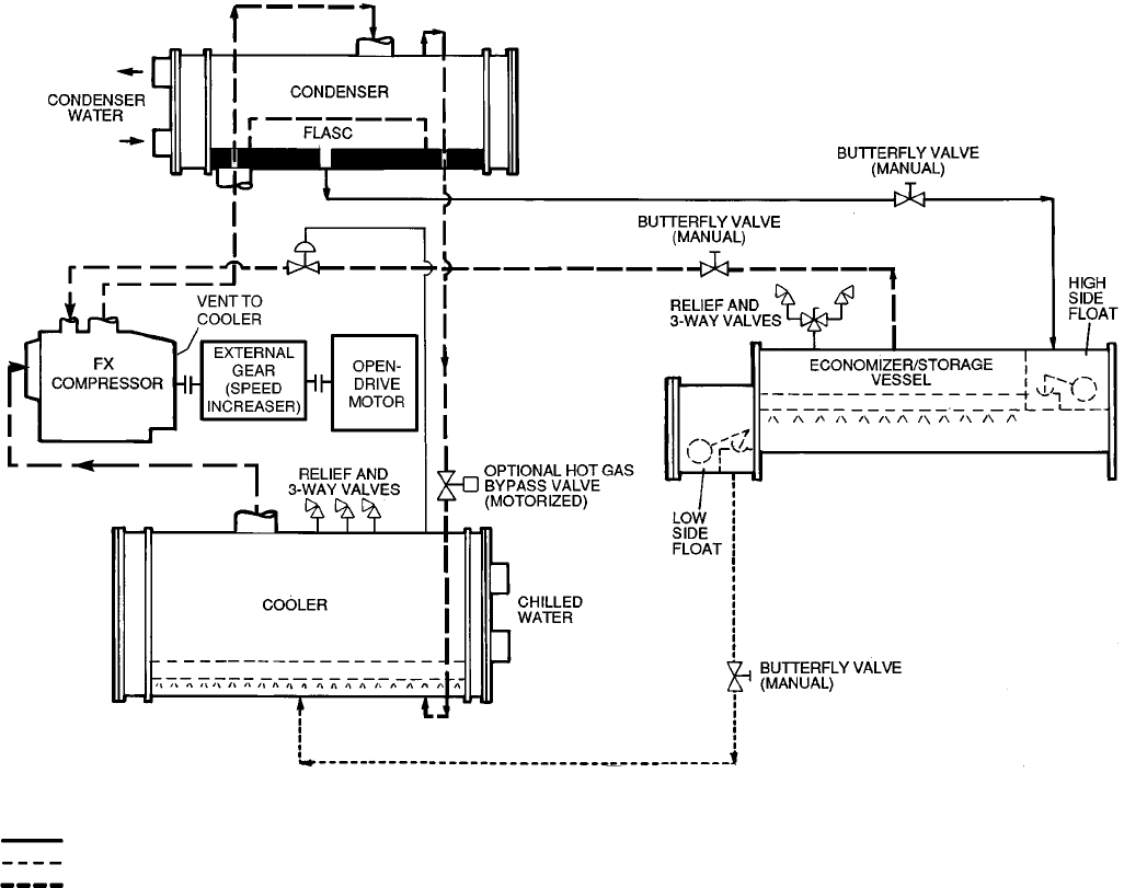
LEGEND
TXV — Thermostatic Expansion Valve
Liquid
Liquid/Vapor
Vapor
*The FX compressor and the gear have a water cooled oil cooler.
Fig. 3 — Refrigeration, Cycle
9