


temperature control overrides, hot gas bypass, surge al-
gorithm status, and time schedule operation. Refer to
Fig. 14 and Table 2, Examples 11-14.
• The control test feature checks for proper operation and
tests the temperature sensors, pressure transducers, the guide
vane actuator, oil pumps, water pumps, tower control, and
other on/off outputs while the compressor is stopped. It
also has the ability to lock off the compressor and turn on
water pumps for pumpout operation. The LID display shows
the required temperatures and pressures during these op-
erations. Refer to Fig. 16 for the CONTROL TEST menu
structure and to the Control Test section, page 85, for more
information on this feature.
• Other SERVICE menu tables can access configured items,
such as chilled water resets, override set points, etc.
• If an operating fault is detected, an alarm message is gen-
erated and displayed on the LID default screen. A more
detailed message, along with a diagnostic message, is also
stored in the ALARM HISTORY table in the PIC.
Checking the Display Messages — The first area
to check when troubleshooting the 17EX is the LID display.
If the alarm light is flashing, check the primary and second-
ary message lines on the LID default screen (Fig. 11). These
messages indicate where the fault is occurring. The ALARM
HISTORY table on the SERVICE menu also carries an alarm
message to further expand on this alarm. For a complete list
of alarm messages, see Table 12. If the alarm light starts to
flash while accessing a menu screen, depress the EXIT
soft-
key to return to the default LID screen to read the failure
message. The compressor does not run while an alarm con-
dition exists unless the alarm type is an unauthorized start or
a failure to shut down.
Checking Temperature Sensors — All tempera-
ture sensors are thermistors. This means that the resistance
of the sensor varies with temperature. All sensors have the
same resistance characteristics. Determine sensor tempera-
ture by measuring voltage drop if the controls are powered,
or resistance if the controls are powered off. Compare the
readings to the values listed in Table 14A or 14B.
RESISTANCE CHECK — Turn off the control power and
disconnect the terminal plug of the sensor in question from
the module. With a digital ohmmeter, measure the sensor re-
sistance between the receptacles designated by the wiring
diagram. The resistance and corresponding temperature are
listed in Table 14Aor 14B. Check the resistance of both wires
to ground. This resistance should be infinite.
VOLTAGE DROP — Using a digital voltmeter, the voltage
drop across any energized sensor can be measured while the
control is energized. Table 14A or 14B lists the relationship
between temperature and sensor voltage drop (volts dc mea-
sured across the energized sensor). Exercise care when mea-
suring voltage to prevent damage to the sensor leads, con-
nector plugs, and modules. The sensor wire should also be
checked at the sensor plug connection. Check the sensor wire
by removing the condenser at the sensor and measure for
5 vdc back to the module, if the control is powered.
Relieve all refrigerant pressure or drain the water prior
to replacing the temperature sensors.
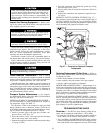
CHECK SENSOR ACCURACY — Place the sensor in a
medium of a known temperature and compare that tempera-
ture to the measured reading. The thermometer used to de-
termine the temperature of the medium should be of labo-
ratory quality with 0.5° F (.25° C) graduations. The sensor
in question should be accurate to within 2° F (1.2° C).
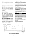
See Fig. 6 for sensor locations. The sensors are immersed
directly in the refrigerant or water circuits. The wiring at each
sensor is easily disconnected by unlatching the connector.
These connectors allow only one-way connection to the sen-
sor. When installing a new sensor, apply a pipe sealant or
thread sealant to the sensor threads.
DUAL TEMPERATURE SENSORS — There are 2 sensing
elements on each of the bearing temperature sensors for ser-
vicing convenience. In case one of the dual sensors is dam-
aged, the other one can be used by moving a wire.
The number 1 terminal in the sensor terminal box is the
common line. To use the second sensor, move the wire from
the number 2 position to the number 3 position.
Checking Pressure Transducers — The 17EX chiller
has 5 transducers. These transducers sense cooler pressure,
condenser pressure, compressor oil supply pressure, oil sump,
and gear oil supply pressure. The compressor oil supply pres-
sure and the oil transmission sump pressure difference is cal-
culated by a differential pressure power supply module. The
PSIO then reads this differential. In effect, then, the
PSIO reads 3 pressure inputs. The cooler and condenser
transducers are used by the PIC to determine refrigerant
temperatures.
All pressure inputs can be calibrated, if necessary. It is not
usually necessary to calibrate at initial start-up. However, at
high altitude locations, calibration of the transducer will be
necessary to ensure the proper refrigerant temperature/
pressure relationship. Each transducer is supplied with 5 vdc
power from a power supply. If the power supply fails, a trans-
ducer voltage reference alarm occurs. If the transducer read-
ing is suspected of being faulty, check the supply voltage. It
should be 5 vdc ± .5 v. If the supply voltage is correct, the
transducer should be re-calibrated or replaced.
To calibrate oil pressure differential, refer to Oil Pressure
Differential Calibration at the end of this section.
Calibration can be checked by comparing the pressure read-
ings from the transducer against an accurate refrigeration gage.
These readings are all viewed or calibrated from the
STATUS01 screen on the LID. The transducer can be checked
and calibrated at 2 pressure points. These calibration points
are 0 psig (0 kPa) and between 240 and 260 psig (1655 to
1793 kPa). To calibrate these transducers:
1. Shut down the compressor.
2. Disconnect the transducer in question from its Schrader
fitting.
NOTE: If the cooler or condenser vessels are at 0 psig
(0 kPa) or are open to atmospheric pressure, the trans-
ducers can be calibrated for zero without removing the
transducer from the vessel.
3. Access the STATUS01 screen, and view the particular trans-
ducer reading; it should read 0 psi (0 kPa). If the reading
is not 0 psi (0 kPa), but within ± 5 psi (35 kPa), the
value may be zeroed by pressing the SELECT
softkey
while the parameter for the transducer is highlighted.
Then, press the ENTER
softkey. The value will now go
to zero.
If the transducer value is not within the calibration range,
the transducer returns to the original reading. If the LID
pressure value is within the allowed range (noted above),
check the voltage ratio of the transducer. To obtain the
voltage ratio, divide the voltage (dc) input from the trans-
ducer by the supply voltage signal, measured at the PSIO
terminals J7-J34 and J7-J35. For example, the condenser
transducer voltage input is measured at PSIO terminals
J7-1 and J7-2. The voltage ratio must be between
0.80 vdc and 0.11 vdc for the software to allow calibra-
tion. Pressurize the transducer until the ratio is within range.
Then attempt calibration again.
84