


CLEANLINESS — On open ventilated motors, screens and
louvers over the inlet air openings should not be allowed to
accumulate any build-up of dirt, lint, etc., that could restrict
free air movement. Screens and louvers should never be cleaned
or disturbed while the motor is in operation because any dis-
lodged dirt or debris can be drawn directly into the motor.
If the motor is equipped with air filters, they should be
replaced (disposable type) or cleaned and reconditioned (per-
manent type) at a frequency that is dictated by conditions. It
is better to replace or recondition filters too often than not
often enough.
Washing motors using a water spray is not recom-
mended. Manual or compressed air cleaning is pre-
ferred. If it becomes necessary to spray-wash a motor,
it should be done with extreme care. Do not aim high
pressure sprays directly at air inlet openings, conduit con-
nections, shaft seals, or gasketed surfaces to prevent the
possibility of forcing water inside the chiller.
The stator windings of motors with open ventilation sys-
tems can become contaminated with dirt and other sub-
stances brought into the motor by the ventilating air. Such
contaminants can impair cooling of the winding by clogging
the air passages in the winding end-turns and vent ducts through
the stator core and by reducing heat transfer from the wind-
ing insulation surfaces to the cooling air. Conducting con-
taminants can change or increase electrical stresses on the
insulation, and corrosive contaminants can chemically at-
tack and degrade the insulation. This may lead to shortened
insulation life and stator failure.
Several satisfactory methods of cleaning stator windings
and stator cores are offered below:
Compressed Air — Low pressure (30 psi maximum), clean
(no oil) dry air can be used to dislodge loose dust and par-
ticles in inaccessible areas such as air vent ducts in the stator
core and vent passages in the winding end-turns. Excessive
air pressure can damage insulation and drive contaminants
into inaccessible cracks and crevices.
Vacuum — Vacuum cleaning can be used, both before and
after other methods of cleaning, to remove loose dirt and
debris. It is a very effective way to remove loose surface
contamination from the winding without scattering it. Vacuum
cleaning tools should be nonmetallic to avoid any damage to
the winding insulation.
Wiping — Surface contamination on the winding can be re-
moved by wiping, using a soft, lint-free wiping material. If
the contamination is oily, the wiping material can be moist-
ened (not dripping wet) with a safety-type petroleum sol-
vent, such as Stoddard solvent. In hazardous locations, a solvent
such as inhibited methyl chloroform may be used, but must
be used sparingly and immediately removed. While this sol-
vent is non-flammable under ordinary conditions, it is toxic.
Proper health and safety precautions should be followed while
using it.
Solvents of any type should never be used on windings
provided with abrasion protection. Abrasion protection is a
grey, rubber-like coating applied to the winding end-turns.
Adequate ventilation must always be provided in any
area where solvents are being used to avoid the danger
of fire, explosion, or health hazards. In confined areas
(such as pits) each operator should be provided with an
air line respirator, a hose mask, or a self-contained breath-
ing apparatus. Operators should wear goggles, aprons,
and suitable gloves. Solvents and their vapors should
never be exposed to open flames or sparks and should
always be stored in approved safety containers.
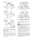
SLEEVE BEARINGS
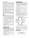
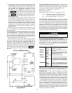
Oil Changing — The oil reservoirs of the self lubricated bear-
ings should be drained and refilled every 6 months. More
frequent changes may be needed if severe oil discoloration
or contamination occurs. In conditions where contamination
does occur, it may be advisable to flush the reservoir with
kerosene to remove any sediment before new oil is added.
Proper care must be taken to thoroughly drain the reservoir
of the flushing material before refilling it with the new oil.
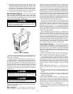
Refill the reservoir to the center of the oil sight glass with
a rust and oxidation inhibited, turbine grade oil. The viscos-
ity of the oil must be 32 ISO (150 SSU) at 100 F (37.7 C).
Oil capacity in each of the 2 bearings is 0.6 gal. (2 l) per
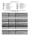
bearing. Use of Carrier Oil Specification PP16-0 is ap-
proved (refer to Table 11).
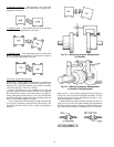
Disassembly — The bearing sleeve is spherically seated and
self-aligning. The opposite drive end bearing is normally in-
sulated for larger motors (or when specified). On some mo-
tors, the insulation is bonded to the spherical seat of the bearing
housing. Use extreme care when removing the sleeve from
the insulated support to avoid damaging this insulation.
Note that some bolts and tapped holes associated with the
bearing housings, bearing sleeves, and seals are metric.
The following procedure is recommended for removing
the bearing sleeve.
1. Remove the oil drain plug in the housing bottom and
drain the oil sump.
2. Remove all instrumentation sensors that are in contact
with the bearing sleeve. These include resistance tem-
perature detectors, thermocouples, temperature relay bulbs,
thermometers, etc.
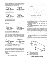
3. Remove the end cover.
4. Remove the socket head bolts holding the bearing cap
and the inner air seal together at the horizontal split. The
front end cover plate must also be removed if the front
bearing is being disassembled. Remove the bearing cap
and top half of the inner air seal by lifting straight up to
avoid damaging the labyrinth seals. Place them on a clean,
dry surface to avoid damage to the parting surfaces.
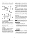
5. Remove any split bolts that may be holding the two bear-
ing halves together. Remove the top half of the bearing
sleeve using suitable eyebolts in the tapped holes pro-
vided. Lift the bearing top straight up and avoid any con-
tact with the shoulders of the shaft journals that might
damage the thrust faces of the bearing. Place on a clean,
dry surface, taking care to prevent damage to either the
parting surfaces or the locating pins that are captive in
the top bearing half.
6. Remove the 4 screws at the partings in the oil ring and
dismantle the ring by gently tapping the dowel pin ends
with a soft-faced mallet. Remove the ring halves and
immediately reassemble them to avoid any mixup in parts
or damage to the surfaces at the partings.
79