


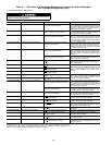
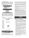
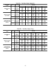
Options Modules (8-Input) — The options modules
are optional additions to the PIC, and are used to add tem-
perature reset inputs, spare sensor inputs, and demand limit
inputs. Each option module contains 8 inputs, each input meant
for a specific duty. See the wiring diagram for exact module
wire terminations. Inputs for each of the options modules
available include the following:
OPTIONS MODULE 1
4 to 20 mAAuto. Demand Reset
4 to 20 mAAuto. Chilled Water Reset
Common Chilled Water Supply Temperature
Common Chilled Water Return Temperature
Remote Temperature Reset Sensor
Spare Temperature 1
Spare Temperature 2
Spare Temperature 3
OPTIONS MODULE 2
4 to 20 mA Spare 1
4 to 20 mA Spare 2
Spare Temperature 4
Spare Temperature 5
Spare Temperature 6
Spare Temperature 7
Spare Temperature 8
Spare Temperature 9
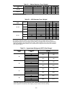
Terminal block connections are provided on the options
modules. All sensor inputs are field wired and installed.
Options module 1 can be factory or field-installed. Options
module 2 is shipped separately and must be field installed.
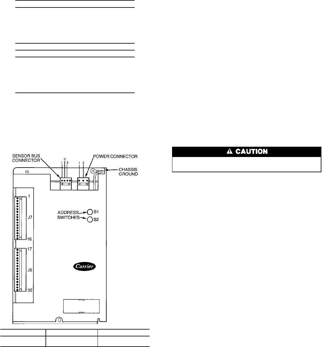
For installation, refer to the unit or field wiring diagrams. Be
sure to address the module for the proper module number
(Fig. 54) and to configure the chiller for each feature being
used.
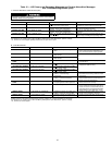
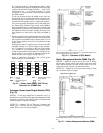
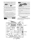
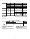
Four-In/Two-Out Module (Fig. 55)
INPUTS — The four analog inputs each have 3 terminals
and are configurable by movable on-board jumpers as ther-
mistor (T), 4 to 20 mA (C), or 0 to 10 vdc (V)
configurations. The inputs monitor the gear oil temperature
and pressure. Input AI#2 should be factory-set with the jumper
on (T). Inputs AI#3, and AI#4 should be factory set on (V).
OUTPUTS — The two analog outputs are each configurable
by on-board jumpers as 0 to 10 vdc (maximum current:
10 mA) or 4 to 20 mA (maximum load: 600 ohms) outputs.
The outputs control the relay that activates the gear oil pump
starter. Outputs AO#1 and AO#2 should be factory set with
the jumper on (V).
This module has a field-configurable DIP (dual in-line pack-
age) switch to designate its address. It should be factory set
with the following switches open: 1, 2, 3, 4, 6, and 8. Switches
5 and 7 should be closed.
Note the SIO bus wiring for this module. Unlike the stand-
ard PIC modules, Pin 2 is negative and Pin 3 is the ground
(or common). See Fig. 51.
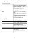
Replacing Defective Processor Modules — The
replacement part number is printed on a small label on the
front of the PSIO module. The model and serial numbers are
printed on the unit nameplate located on an exterior corner
post. The proper software is factory-installed by Carrier in
the replacement module. When ordering a replacement pro-
cessor module (PSIO), specify complete replacement part num-
ber, full unit model number, and serial number. This new
unit requires reconfiguration to the original chiller data by
the installer. Follow the procedures described in the Set Up
Chiller Control Configuration section on page 54. Electrical
shock can cause personal injury. Disconnect all electrical power
before servicing.
Electrical shock can cause personal injury. Disconnect
all electrical power before servicing.
INSTALLATION OF NEW PSIO MODULE
1. Verify that the existing PSIO module is defective by us-
ing the procedure described in the Notes on Module Op-
eration section, page 96, and the Control Modules sec-
tion, page 96. Do not access theATTACH TO NETWORK
DEVICE screen if the LID displays a communication
failure.
2. Data regarding the PSIO configuration should have been
recorded and saved. This data must be reconfigured into
the LID. If this data is not available, follow the proce-
dures described in the Set Up Chiller Control Configu-
ration section, page 54. Record the TOTAL COMPRES-
SOR STARTS and the COMPRESSOR ONTIME from the
STATUS01 table on the LID.
If a CCN Building Supervisor or Service Tool is present,
the module configuration should have already been up-
loaded into memory; then, when the new module is in-
stalled, the configuration can be downloaded from the
computer (if the software version is the same).
Any communication wires from other chillers or CCN
modules must be disconnected.
3. Check that all power to the unit is off. Carefully dis-
connect all wires from the defective module by unplug-
ging the 6 connectors. It is not necessary to remove any
of the individual wires from the connectors.
4. Remove the defective PSIO by removing its mounting
screw with a long-shaft Phillips screwdriver and remov-
ing the module from the control box. Save the screw for
later use. The green ground wire is held in place with
the module mounting screw.
5. Package the defective module in the carton of the new
module for return to Carrier.
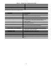
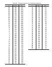
SWITCH SETTING OPTIONS MODULE 1 OPTIONS MODULE 2
S1 67
S2 42
Fig. 54 — Options Module
98