


2. Parallel in elevation — This alignment is also made with
shims, but it cannot be made while there is angular mis-
alignment in elevation.
3. Angular in plan — This position can easily be lost if placed
ahead of the two adjustments in elevation.
4. Parallel in plan — This adjustment cannot be made while
there is still angular misalignment in plan and can easily be
lost if elevation adjustments are made.
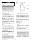
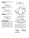
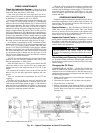
Correcting Angular Misalignment
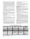
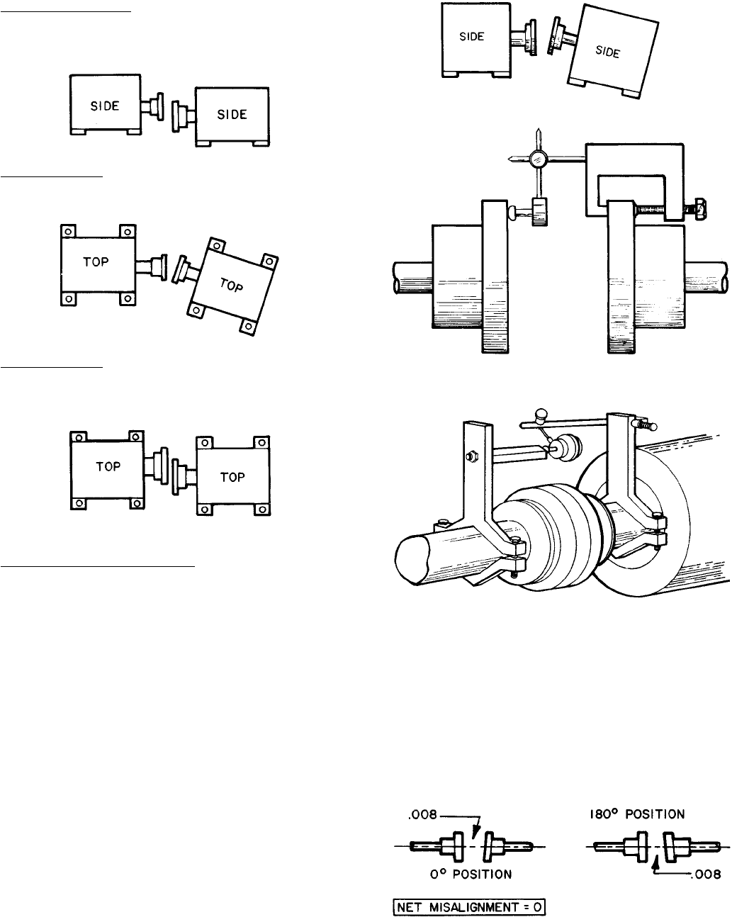
Preparation — Shaft angular misalignment is measured on
the face of the coupling hubs or on brackets attached to each
shaft (see Fig. 38 and 39). Brackets are preferred since they
extend the diameter of the face readings.
Attach a dial indicator to one coupling hub or shaft and
place the indicator button against the face of the opposite
hub. Position the indicator so that the plunger is at approxi-
mately mid-position when the dial is set to zero. Both shafts
should be held tightly against their thrust bearings when the
dial is set and when readings are taken.
To be sure that the indicator linkage is tight and the button
is on securely, rotate the coupling exactly 360 degrees. The
dial reading should return to zero. Accept only repeatable
readings.
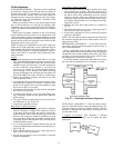
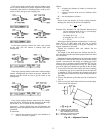
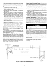
Measurement — Occasionally, coupling faces may not be per-
fectly true or may have been damaged in handling. To com-
pensate for any such runout, determine the actual or ‘‘net’’
shaft misalignment as follows:
Check the opening at the top and at the bottom of the cou-
pling faces (or at each side when making plan adjustment).
Rotate both shafts exactly 180 degrees and recheck the open-
ings. Record the difference. (Example below is in inches.)
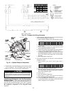
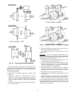
Fig. 38 — Measuring Angular Misalignment
in Elevation
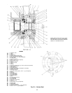
Fig. 39 — Measuring Angular Misalignment
in Elevation Using Brackets
72