


4. A high pressure point can also be calibrated between 240
and 260 psig (1655 and 1793 kPa) by attaching a regu-
lated 250 psig (1724 kPa) pressure (usually from a ni-
trogen cylinder). The high pressure point can be calibrated
by accessing the appropriate transducer on the
STATUS01 screen, highlighting the transducer, pressing
the SELECT
softkey, and then increasing or decreasing
the value to the exact pressure on the refrigerant gage.
Press ENTER
to finish. High altitude locations must com-
pensate the pressure so that the temperature/pressure re-
lationship is correct.
If the transducer reading returns to the previous value and
the pressure is within the allowed range, check the volt-
age ratio of the transducer. Refer to Step 3 above. The
voltage ratio for this high pressure calibration must be
between 0.585 and 0.634 vdc to allow calibration. Change
the pressure at the transducer until the ratio is within the
acceptable range. Then attempt to calibrate to the new
pressure input.
The PIC will not allow calibration if the transducer is too
far out of calibration. A new transducer must be installed
and re-calibrated.
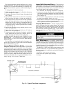
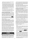
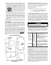
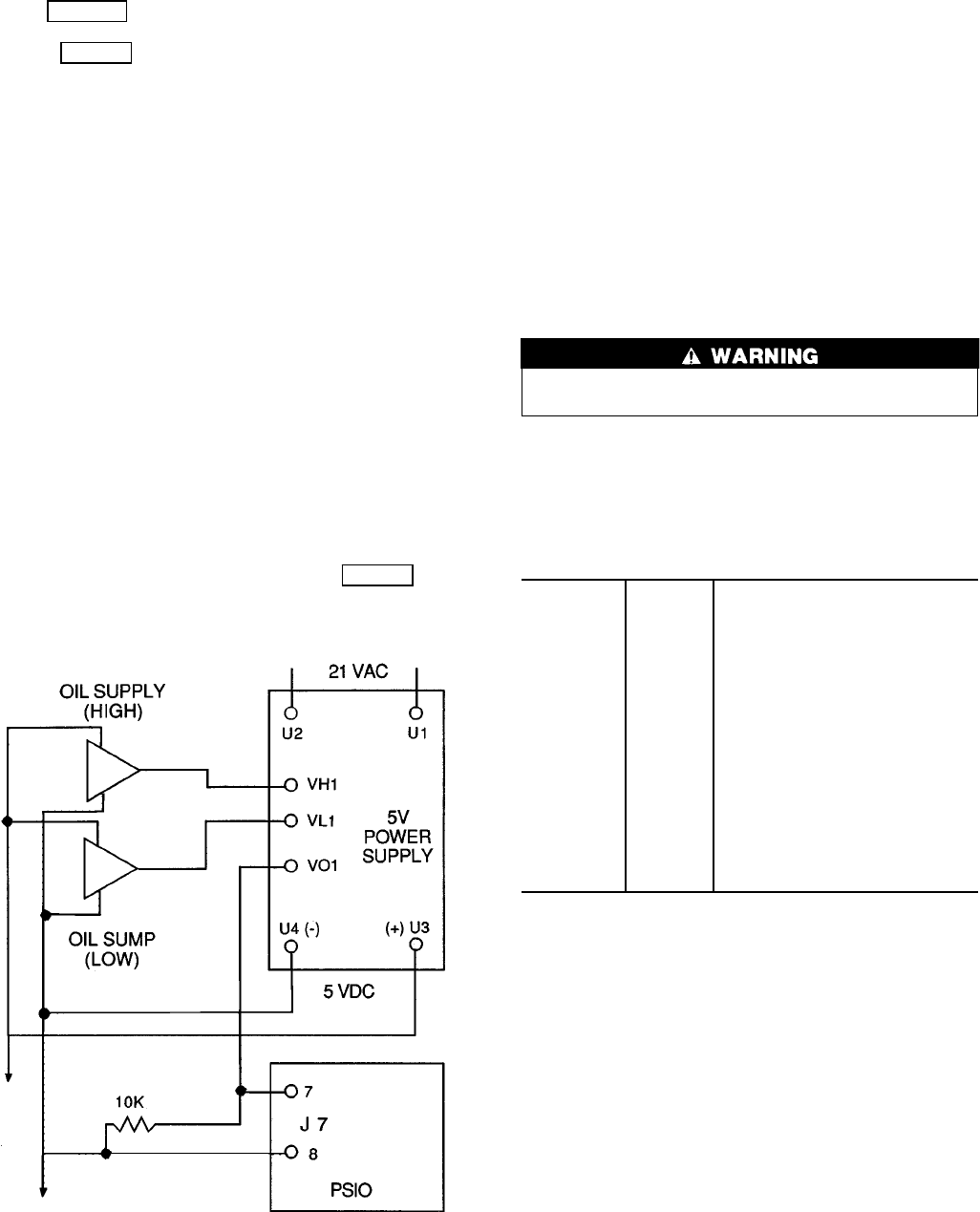
OIL DIFFERENTIALPRESSURE/POWER SUPPLY MOD-
ULE CALIBRATION — (See Fig. 48.) The oil reservoir in
the 17EX chiller is not common to cooler pressure. There-
fore, a comparison of pump output to cooler pressure can
not be used to provide differential oil pressure information.
A different method has been developed.
Oil transmission sump pressure and oil supply pressure
are fed to a comparator circuit on a 5V power supply board.
The output of this circuit, which represents differential oil
pressure, is fed to the PSIO. The oil differential pressure is
calibrated to 0 psid (0 kPad) by selecting the oil pressure
input on the STATUS01 screen. Then, with the oil pump turned
OFF and the transducers connected, press the ENTER
soft-
key to zero the point. No high end calibration is needed or
possible.
TROUBLESHOOTING TRANSDUCERS — When trouble-
shooting transducers, keep the negative lead of your volt-
ohmmeter on terminal U4 of the power supply (or terminal
4 on power supplies without the comparator circuit).
Voltage VO1 = (VH1-VL1) + .467 ± .1 V
For all PIC transducers:
Measured pressure = (507.97 × (V
out
/V
in
)) − 47.33
V
out
= transducer output ref. to neg. terminal
(4 or U4) i.e., VH1 to U4 or VL1 to U4
V
in
= power supply output, i.e., U3 to U4
TRANSDUCER REPLACEMENT — Since the transduc-
ers are mounted on Schrader-type fittings, there is no need
to remove refrigerant from the vessel. Disconnect the trans-
ducer wiring by pulling up on the locking tab while pulling
up on the weather-tight connecting plug from the end of the
transducer. Do not pull on the transducer wires. Unscrew
the transducer from the Schrader fitting. When installing a
new transducer, do not use pipe sealer, which can plug the
sensor. Put the plug connector back on the sensor and snap
into place. Check for refrigerant leaks.
Make sure to use a backup wrench on the Schrader fit-
ting whenever removing a transducer.
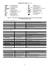
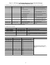
Control Algorithms Checkout Procedure — One
of the tables in the SERVICE menu is the CONTROL AL-
GORITHM STATUS table. This table has 6 screens that may
be viewed to see how a particular control algorithm is
operating, that is, to see what parameters and values the PIC
is using to control the chiller.
MAINT01 Capacity
Control
Thevalues usedto calculatethe chilled
water/brine control point.
MAINT02 Override
Status
Details ofall chilledwater controlover-
ride values
MAINT03 Surge/
HGBP
Status
The surge and hot gas bypass control
algorithm status as well as the values
dealing with this control.
MAINT04 LEAD/LAG
Status
LEAD/LAG operation status.
OCCDEFM Time
Schedules
Status
The Local and CCN occupied sched-
ules, displayedin away thatallows the
operator to quicklydetermine whether
the schedule is in an occupied period
or not.
WSMDEFME Water
System
Manager
Status
The status of the WSM (water system
manager), aCCN modulethat canturn
on the chiller and change the chilled
water control point.
These maintenance tables are very useful in determining
guide vane position, reaction from load changes, control point
overrides, hot gas bypass reaction, surge prevention, etc.
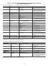
Control Test — The control test feature can check all
the thermistor temperature sensors, including those on the
Options modules, pressure transducers, pumps and their as-
sociated flow switches, the guide vane actuator, and other
control outputs, such as hot gas bypass. The tests can help
to determine whether a switch is defective, or a pump relay
is not operating, among other useful troubleshooting tests.
During pumpdown operations, the pumps are energized
to prevent freeze-up, and the vessel pressures and tempera-
tures are displayed. The pumpdown/lockout feature pre-
vents the compressor from starting up when there is no re-
frigerant in the chiller or when the vessels are isolated. The
operator then uses the terminate lockout screen to end the
pumpdown lockout after the pumpdown procedure is re-
versed and refrigerant is added.
Fig. 48 — Oil Differential Pressure/Power
Supply Module
17EX OIL PRESSURE INPUT
85