


If all modules indicate a communications failure, check
the communications plug on the PSIO module for proper
seating. Also check the wiring (CCN bus — 1:red, 2:wht,
3:blk; Sensor bus — 1:red, 2:blk, 3:clr/wht). If a good
connection is assured and the condition persists, replace
the PSIO module.
If only one 8-input module, the SMM, or the 4-in/2-out
module indicates a communication failure, check the com-
munications plug on that module. If a good connection is
assured and the condition persists, replace the module.
All system operating intelligence rests in the PSIO mod-
ule. Some safety shutdown logic resides in the SMM in
case communications are lost between the 2 modules. The
PSIO monitors conditions using input ports on the PSIO,
the SMM, the 8-input modules, and the 4-in/2-out mod-
ules. Outputs are controlled by the PSIO and SMM as
well.
3. Power is supplied to the modules within the control panel.
The transformers are located within the power panel, with
the exception of the SMM, which operates from a 24-vac
power source and has its own 24-vac transformer located
in the starter.
In the power panel, T1 supplies power 21-vac to the LID,
the PSIO, and the 5-vac power supply for the transduc-
ers. T3 supplies 24-vac power to the 4-in/2-out module.
T4 is another 21-vac transformer, which supplies power
to both 8-input modules (if present). T4 is capable of sup-
plying power to two modules; if additional modules are
added, another power supply will be required.
Power is connected to Terminals 1 and 2 of the power
input connection on each module.
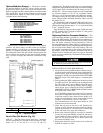
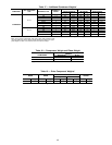
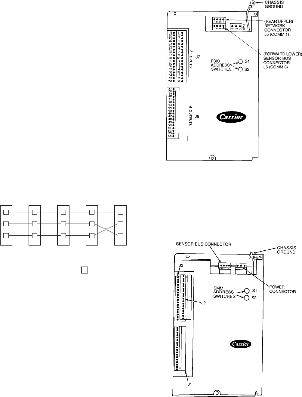
Processor/Sensor Input/Output Module (PSIO)
(Fig. 52)
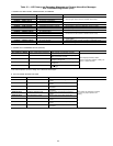
INPUTS — Each input channel has 3 terminals; only 2 of
the terminals are used. The chiller application determines which
terminals are normally used. Always refer to individual unit
wiring diagrams for terminal numbers.
OUTPUTS — Output is 20 vdc. There are 3 terminals per
output, only 2 of which are used, depending on the appli-
cation. Refer to the unit wiring diagram.
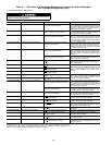
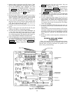
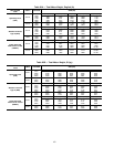
Starter Management Module (SMM) (Fig. 53)
INPUTS — Inputs on strips J2 and J3 are a mix of analog
and discrete (on/off) inputs. The chiller application deter-
mines which terminals are used. Always refer to the indi-
vidual unit wiring diagram for terminal numbers.
OUTPUTS — Outputs are 24 vdc and wired to strip J1. There
are 2 terminals used per output.
1
2
3
1
2
3
1
2
3
1
2
3
1
2
3
PSIO (J8)
SMM (J5)
8-INPUT (J5)
8-INPUT (J5)
4-IN/2-OUT (J3)
GRD
GRD
GRD
GRD
GRD
+
+
+
+
-
-
-
-
+
-
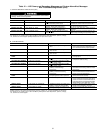
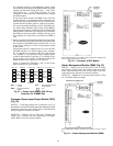
LEGEND
GRD — Ground
J—Junction
SMM — Starter Management
Module
PSIO — Processor/Sensor Input/
Output Module
Pins
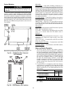
Fig. 51 — Sensor Input/Output (SIO) Wiring
Schematic for COMM3 Bus
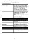
NOTE:Addressswitcheson thismodulecan beatany position.Addresses can
only be changed through the LID or CCN.
Fig. 52 — Processor (PSIO) Module
NOTE: SMM address switches should be set as follows: S1 set at 3; S2 set
at 2.
Fig. 53 — Starter Management Module (SMM)
97